Nissan Maxima Service and Repair Manual: Climate controlled seat system
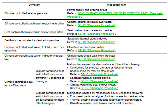
Symptom Table

 Squeak and rattle trouble diagnoses
Work Flow
CUSTOMER INTERVIEW
Interview the customer if possible, to determine the conditions that exist
when the noise occurs. Use the Diagnostic
Worksheet during the interview to document the ...
Other materials:
Subwoofer
Removal and Installation
Subwoofer (LH)
Subwoofer (RH)
Subwoofer screws
Subwoofer connectors
REMOVAL
Remove the rear parcel shelf finisher. Refer to INT-28, "Removal
and Installation".
Remove the subwoofer screws.
Pull out the subwoofer, disconnect the harness con ...
P1564 ASCD steering switch
Description
ASCD steering switch has variant values of electrical resistance for each
button. ECM reads voltage variation
of switch, and determines which button is operated.
Refer to EC-68, "System Diagram" for the ASCD function.
DTC Logic
DTC DETECTION LOGIC
NOTE:
If DTC P156 ...
Precaution
PRECAUTIONS
Precaution for Supplemental Restraint System (SRS) "AIR BAG" and
"SEAT BELT PRE-TENSIONER"
The Supplemental Restraint System such as "AIR BAG" and "SEAT BELT
PRE-TENSIONER", used along with a front seat belt, helps to reduce the risk
or severity of injury to the driver and front ...
Nissan Maxima Owners Manual
- Illustrated table of contents
- Safety-Seats, seat belts and supplemental restraint system
- Instruments and controls
- Pre-driving checks and adjustments
- Monitor, climate, audio, phone and voice recognition systems
- Starting and driving
- In case of emergency
- Appearance and care
- Do-it-yourself
- Maintenance and schedules
- Technical and consumer information
Nissan Maxima Service and Repair Manual

0.0086