Nissan Maxima Service and Repair Manual: Basic inspection
DIAGNOSIS AND REPAIR WORK FLOW
Work Flow
OVERALL SEQUENCE
DETAILED FLOW
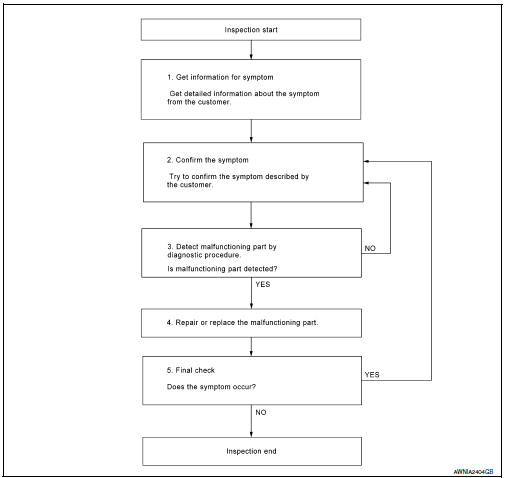
1.GET INFORMATION FOR SYMPTOM
Get detailed information from the customer about the symptom (the condition and the environment when the incident/malfunction occurred).
2.CONFIRM THE SYMPTOM
Try to confirm the symptom described by the customer. Verify relation between the symptom and the condition when the symptom is detected. Refer to SE-51, "Symptom Table".
3.DETECT MALFUNCTIONING PART BY DIAGNOSTIC PROCEDURE
Inspect according to Diagnostic Procedure of the system.
4.REPAIR OR REPLACE THE MALFUNCTIONING PART
- Repair or replace the malfunctioning part.
- Reconnect parts or connectors disconnected during Diagnostic Procedure.
5.FINAL CHECK
Refer to confirmed symptom in step 2, and make sure that the symptom is not detected.
 Seat
Seat
...
 System description
CLIMATE CONTROLLED SEAT SYSTEM
System Diagram
System Description
The climate controlled seat system is controlled by the climate
controlled seat control unit.
Operation of the climate co ...
Other materials:
Diagnosis and repair workflow
Work Flow
WORK FLOW
DETAILED FLOW
1. GET INFORMATION FOR SYMPTOM
Get the detailed information from the customer about the symptom (the
condition and the environment when the incident/malfunction occurred).
2. CHECK DTC
Check DTC.
Perform the following procedure if DTC is displayed.
...
Bluetooth control unit
Removal and Installation
REMOVAL
Disconnect the battery negative terminal.
Remove the trunk upper finisher. Refer to INT-36, "Exploded View".
Remove the parcel shelf finisher. Refer to INT-28, "Removal and
Installation".
From inside the passenger compartment, remove the bracket screw ...
Precaution
Precaution for Supplemental Restraint System (SRS) "AIR BAG" and
"SEAT BELTPRE-TENSIONER"
The Supplemental Restraint System such as "AIR BAG" and "SEAT BELT
PRE-TENSIONER", used alongwith a front seat belt, helps to reduce the risk
or severity of injury to the driver and front passenger for c ...
Nissan Maxima Owners Manual
- Illustrated table of contents
- Safety-Seats, seat belts and supplemental restraint system
- Instruments and controls
- Pre-driving checks and adjustments
- Monitor, climate, audio, phone and voice recognition systems
- Starting and driving
- In case of emergency
- Appearance and care
- Do-it-yourself
- Maintenance and schedules
- Technical and consumer information
Nissan Maxima Service and Repair Manual

0.0426