Nissan Maxima Service and Repair Manual: System description
CLIMATE CONTROLLED SEAT SYSTEM
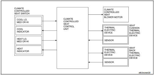
System Diagram
System Description
- The climate controlled seat system is controlled by the climate controlled seat control unit.
- Operation of the climate controlled seat switch sends heated or cooled airflow and adjusts the seat temperature.
SEAT CUSHION AND SEATBACK TEMPERATURE ADJUSTMENT FUNCTION
- A thermal electric device (TED) unit is installed in the seat cushion and seatback. The device heats or cools, sends airflow to the seat surface, and adjusts the seat temperature.
- The thermal electric device (TED) is a heat exchanger that has a function to heat or cool the airflow from the climate controlled seat blower motor. By changing the direction of the current from the power supply, the device takes or gives heat, and adjusts the heat exchange process depending on voltage.
NOTE:
The climate controlled seat blower motor maintains low speed for approximately 60 seconds after turning the climate controlled seat switch off.
CAUTION:
- The thermal electric device has a dual-climate function that allows one side to operate at a high temperature and the other to operate at a low temperature simultaneously.
- Before starting work, always turn OFF the switch and check that the thermal electric device is cold.
FAIL-SAFE
The fail-safe function is adopted for the climate controlled seat control unit. Refer to SE-26, "Fail-safe".
Component Parts Location
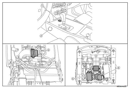
- Climate controlled seat switch M302
- Climate controlled seat relay M58
- Seatback thermal electric device B218
- Seat cushion thermal electric device B219
- Climate controlled seat control unit B212, B216, B217
- Climate controlled seat blower motor B220
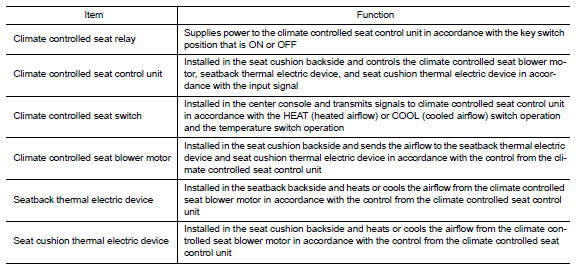
Component Description
 Basic inspection
DIAGNOSIS AND REPAIR WORK FLOW
Work Flow
OVERALL SEQUENCE
DETAILED FLOW
1.GET INFORMATION FOR SYMPTOM
Get detailed information from the customer about the symptom (the condition
and the envir ...

Other materials:
Front power seat adjustment
Operating tips
The power seat motor has an auto-reset
overload protection circuit. If the motor
stops during operation, wait 30 seconds
then reactivate the switch.
Do not operate the power seat switch for a
long period of time when the engine is off.
This will discharge the bat ...
U1000 CAN comm circuit
Description
CAN (Controller Area Network) is a serial communication line for real time
application. It is an on-vehicle multiplex
communication line with high data communication speed and excellent error
detection ability. Many electronic
control units are equipped onto a vehicle, and each ...
B1145 - B1148 side curtain air bag module RH
Description
DTC B1145 - B1148 RH SIDE CURTAIN AIR BAG MODULE
The RH side curtain air bag module is wired to the air bag diagnosis sensor
unit. The air bag diagnosis sensorunit will monitor for opens and shorts in
detected lines to the RH side curtain air bag module.
PART LOCATION
DTC Logic
...
Nissan Maxima Owners Manual
- Illustrated table of contents
- Safety-Seats, seat belts and supplemental restraint system
- Instruments and controls
- Pre-driving checks and adjustments
- Monitor, climate, audio, phone and voice recognition systems
- Starting and driving
- In case of emergency
- Appearance and care
- Do-it-yourself
- Maintenance and schedules
- Technical and consumer information
Nissan Maxima Service and Repair Manual

0.0053