Nissan Maxima Service and Repair Manual: Sound signal circuit
SATELLITE RADIO TUNER
SATELLITE RADIO TUNER : Description
Left and right channel audio signals are supplied from the satellite radio tuner to the AV control unit through the sound signal circuits.
SATELLITE RADIO TUNER : Diagnosis Procedure
LEFT CHANNEL
1.CHECK HARNESS
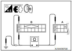
- Turn ignition switch OFF.
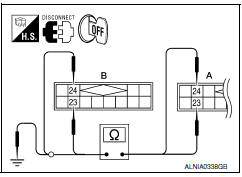
- Disconnect satellite radio tuner (factory installed) connector B111 and AV control unit connector M116.
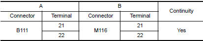
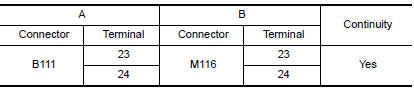
- Check continuity between satellite radio tuner (factory installed) connector B111 (A) and AV control unit connector M116 (B).
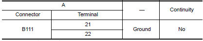
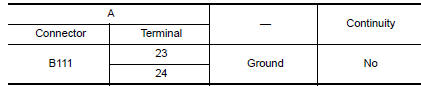
- Check continuity between satellite radio tuner (factory installed) connector B111 (A) and ground.
2.CHECK LEFT CHANNEL AUDIO SIGNAL

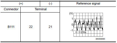
- Connect satellite radio tuner (factory installed) and AV control unit.
- Turn ignition switch ON.
- Check signal between satellite radio tuner (factory installed) connector B111 terminals 21 and 22 with CONSULT or oscilloscope.
RIGHT CHANNEL
1.CHECK HARNESS
- Turn ignition switch OFF.
- Disconnect satellite radio tuner (factory installed) connector B111 and AV control unit connector M116.
- Check continuity between satellite radio tuner (factory installed) B111 (A) and AV control unit M116 (B).
- Check continuity between satellite radio tuner (factory installed) connector B111 (A) and ground.
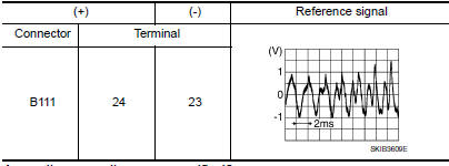
2.CHECK RIGHT CHANNEL AUDIO SIGNAL
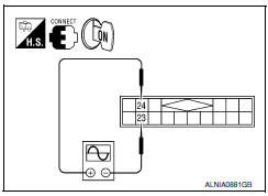
- Connect satellite radio tuner (factory installed) and AV control unit.
- Turn ignition switch ON.
- Check signal between satellite radio tuner (factory installed) connector B111 terminals 23 and 24 with CONSULT or oscilloscope.
 Communication signal circuit
SATELLITE RADIO TUNER
SATELLITE RADIO TUNER : Description
Communication signals are exchanged between the AV control unit and satellite
radio tuner using the communication circuits.
SATELLITE RAD ...
 Microphone signal circuit
Description
Voice signals are transmitted from the microphone to the Bluetooth control
unit using the microphone signal circuits.
Diagnosis Procedure
1.CHECK HARNESS BETWEEN BLUETOOTH CONTROL UNI ...
Other materials:
Power seat for passenger side
Wiring Diagram
...
B257B, B257C ambient sensor
Description
COMPONENT DESCRIPTION
Ambient Sensor
The ambient sensor (1) is installed to the front bumper
reinforcement.
It detects ambient temperature and converts it into a resistance
value which is then input into the A/C auto amp.
Ambient Sensor Circuit
AMBIENT TEMPERATUR ...
Heater and Air Conditioner (automatic)
Front defroster button
Temperature control dial (driver's side)/
AUTO button
Display screen
Temperature control dial (passenger's
side)/DUAL button
Fresh air intake button
Air recirculation button
(air conditioner) button
(manual air flow control)
button
(fan speed cont ...
Nissan Maxima Owners Manual
- Illustrated table of contents
- Safety-Seats, seat belts and supplemental restraint system
- Instruments and controls
- Pre-driving checks and adjustments
- Monitor, climate, audio, phone and voice recognition systems
- Starting and driving
- In case of emergency
- Appearance and care
- Do-it-yourself
- Maintenance and schedules
- Technical and consumer information
Nissan Maxima Service and Repair Manual

0.0064