Nissan Maxima Service and Repair Manual: Communication signal circuit
SATELLITE RADIO TUNER
SATELLITE RADIO TUNER : Description
Communication signals are exchanged between the AV control unit and satellite radio tuner using the communication circuits.
SATELLITE RADIO TUNER : Diagnosis Procedure
1.CHECK HARNESS - 1
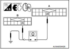
- Turn ignition switch OFF.
- Disconnect satellite radio tuner (factory installed) connector B111 and AV control unit connector M116.
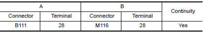
- Check continuity between satellite radio tuner (factory installed) harness connector B111 (A) terminal 28 and AV control unit harness connector M116 (B) terminal 28.
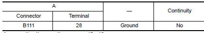
- Check continuity between satellite radio tuner (factory installed) harness connector B111 (A) terminal 28 and ground.
2.CHECK HARNESS - 2
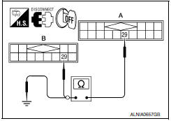
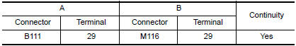
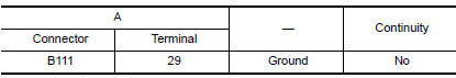
- Check continuity between satellite radio tuner (factory installed) harness connector B111 (A) terminal 29 and AV control unit harness connector M116 (B) terminal 29.
- Check continuity between satellite radio tuner (factory installed) harness connector B111 (A) terminal 29 and ground.
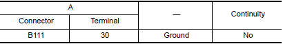
3.CHECK HARNESS - 3
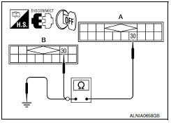
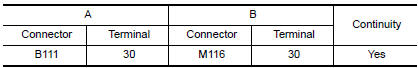
- Check continuity between satellite radio tuner (factory installed) harness connector B111 (A) terminal 30 and AV control unit harness connector M116 (B) terminal 30.
- Check continuity between satellite radio tuner (factory installed) harness connector B111 (A) terminal 30 and ground.
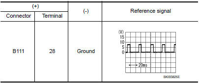
4.CHECK REQ1 SIGNAL
- Connect satellite radio tuner (factory installed) connector and AV control unit connector.
- Turn ignition switch to ACC.
- Check signal between satellite radio tuner (factory installed) harness connector B111 terminal 28 and ground with CONSULT or oscilloscope.
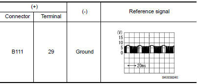
5.CHECK TXD SIGNAL
Check signal between satellite radio tuner (factory installed) harness connector B111 terminal 29 and ground with CONSULT or oscilloscope.
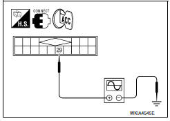
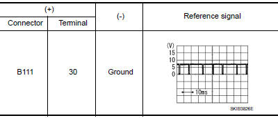
6.CHECK RXD SIGNAL
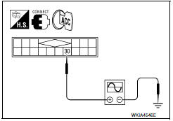
Check signal between satellite radio tuner (factory installed) harness connector B111 terminal 30 and ground with CONSULT or oscilloscope.
 Steering switch
Description
When one of the steering wheel audio control switches is pushed, the
resistance in the steering wheel audio control switch circuit changes,
depending on which button is pushed.
Diagn ...
 Sound signal circuit
SATELLITE RADIO TUNER
SATELLITE RADIO TUNER : Description
Left and right channel audio signals are supplied from the satellite radio
tuner to the AV control unit through the sound signal circuits. ...
Other materials:
Remote keyless entry receiver
Removal and Installation
REMOVAL
Remove glove box assembly. Refer to IP-20, "Removal and
Installation".
Disconnect the harness connector from the remote keyless
entry receiver (1).
Remove the screw (a) and remote keyless entry receiver (1).
INSTALLATION
Installation ...
Remote Engine Start
The button will be on the NISSAN
Intelligent
Key if the vehicle has remote engine start.
This feature allows the engine to start from outside
the vehicle.
The following features may be affected when the
remote start feature is used:
Vehicles with an automatic climate control
sys ...
Inspection and adjustment
ADDITIONAL SERVICE WHEN REMOVING BATTERY NEGATIVE TERMINAL
ADDITIONAL SERVICE WHEN REMOVING BATTERY NEGATIVE TERMINAL : Description
Initial setting is necessary when battery terminal is removed.
CAUTION:
The following specified operations are not performed under the
non-initialized condition. ...
Nissan Maxima Owners Manual
- Illustrated table of contents
- Safety-Seats, seat belts and supplemental restraint system
- Instruments and controls
- Pre-driving checks and adjustments
- Monitor, climate, audio, phone and voice recognition systems
- Starting and driving
- In case of emergency
- Appearance and care
- Do-it-yourself
- Maintenance and schedules
- Technical and consumer information
Nissan Maxima Service and Repair Manual

0.0064