Nissan Maxima Service and Repair Manual: Steering switch
Description
When one of the steering wheel audio control switches is pushed, the resistance in the steering wheel audio control switch circuit changes, depending on which button is pushed.
Diagnosis Procedure
1.CHECK STEERING SWITCH RESISTANCE
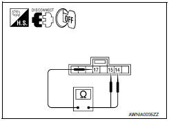
- Disconnect steering switch connector M88.
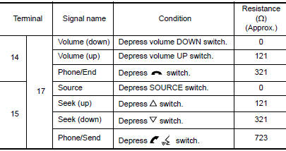
- Check resistance between steering switch connector terminals.
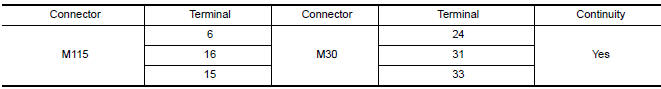
2.CHECK HARNESS BETWEEN COMBINATION SWITCH (SPIRAL CABLE) AND AV CONTROL UNIT
- Disconnect AV control unit connector M115.
- Check continuity between AV control unit harness connector M115 and combination switch (spiral cable) harness connector M30.
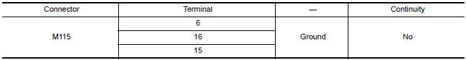
- Check continuity between AV control unit connector M115 and ground.
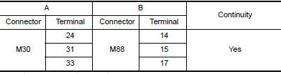
3.COMBINATION SWITCH (SPIRAL CABLE) CHECK
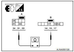
- Disconnect combination switch (spiral cable) connector M88.
- Check continuity between combination switch (spiral cable) harness connector M30 (A) and M88 (B).
 Subwoofer
Description
The AV control unit sends audio signals to the subwoofer amp. The subwoofer
amp. amplifies the audio signals before sending them to the subwoofers using
the audio signal circuits.
Di ...
 Communication signal circuit
SATELLITE RADIO TUNER
SATELLITE RADIO TUNER : Description
Communication signals are exchanged between the AV control unit and satellite
radio tuner using the communication circuits.
SATELLITE RAD ...
Other materials:
Parking brake shoe
Exploded View
Back plate
Parking brake shoe (front)
Adjuster
Adjuster spring
Return spring
Anti-rattle spring
Retainer
Anti-rattle pin
Toggle lever
Parking brake shoe (rear)
Front
Apply PBC (Poly Butyl Cuprysil)
grease or silicone based grease
Removal ...
P1720 VSS
Description
ECM receives two vehicle speed signals via the CAN communication line. One is
sent from "ABS actuator and
electric unit (control unit)" via the combination meter, and the other is from
TCM (Transmission control module).
ECM uses these signals for engine control.
DTC Logic
DTC ...
Blower motor
Description
COMPONENT DESCRIPTION
Brush-less Motor
The blower motor utilizes a brush-less motor with a rotating magnet.
Quietness is improved over previous motors where the brush was
the point of contact and the coil rotated.
Blower Motor Circuit
Component Function Check
1.CHECK OP ...
Nissan Maxima Owners Manual
- Illustrated table of contents
- Safety-Seats, seat belts and supplemental restraint system
- Instruments and controls
- Pre-driving checks and adjustments
- Monitor, climate, audio, phone and voice recognition systems
- Starting and driving
- In case of emergency
- Appearance and care
- Do-it-yourself
- Maintenance and schedules
- Technical and consumer information
Nissan Maxima Service and Repair Manual

0.0054