Nissan Maxima Service and Repair Manual: Subwoofer
Description
The AV control unit sends audio signals to the subwoofer amp. The subwoofer amp. amplifies the audio signals before sending them to the subwoofers using the audio signal circuits.
Diagnosis Procedure
1.CONNECTOR CHECK
Check the AV control unit, subwoofer amp. and subwoofer connectors for the following:
- Proper connection
- Damage
- Disconnected or loose terminals
2.HARNESS CHECK
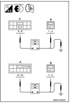
- Disconnect subwoofer amp. connector B21 and suspect subwoofer connector.
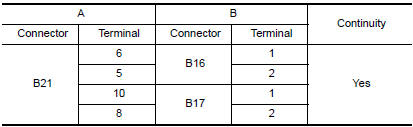
- Check continuity between subwoofer amp. harness connector B21 (A) and suspect subwoofer harness connector (B).
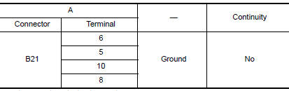
- Check continuity between subwoofer harness connector B21 (A) and ground.
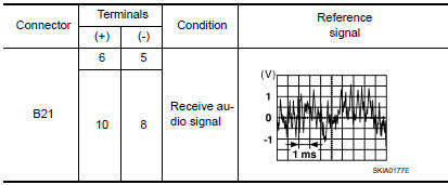
3.REAR SUBWOOFER SIGNAL CHECK
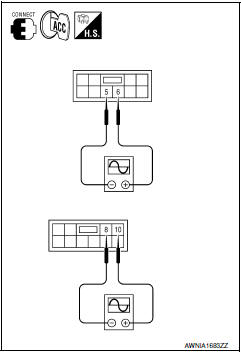
- Connect subwoofer amp. connector B21 and suspect subwoofer connector.
- Turn ignition switch to ACC.
- Push POWER switch.
- Check the signal between subwoofer amp. harness connector B21 terminals with CONSULT or oscilloscope.
4.HARNESS CHECK
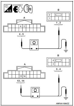
- Disconnect AV control unit connector M115 and subwoofer speaker amp. connector B21.
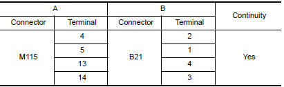
- Check continuity between AV control unit harness connector M115 (A) and subwoofer amp. harness connector B21 (B).
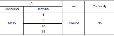
- Check continuity between AV control unit harness connector M115 (A) terminal and ground
5.SUBWOOFER SIGNAL CHECK
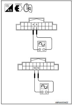
- Connect AV control unit connector M115 and subwoofer amp.
connector B21.
- Turn ignition switch to ACC.
- Push "POWER" switch.
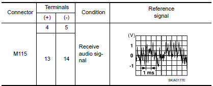
- Check the signal between AV control unit harness connector M115 terminals with CONSULT or oscilloscope.
 Rear door speaker
Description
The AV control unit sends audio signals to the rear door speakers using the
rear door speaker circuits.
Diagnosis Procedure
1.CONNECTOR CHECK
Check the AV control unit and speaker co ...
 Steering switch
Description
When one of the steering wheel audio control switches is pushed, the
resistance in the steering wheel audio control switch circuit changes,
depending on which button is pushed.
Diagn ...
Other materials:
HVAC branch line circuit
Diagnosis Procedure
1.CHECK CONNECTOR
Turn the ignition switch OFF.
Disconnect the battery cable from the negative terminal.
Check the terminals and connectors of the A/C auto amp. for
damage, bend and loose connection (unit
side and connector side).
2.CHECK HARNESS FOR OPEN CIRCUI ...
A/C switch assembly signal circuit
Diagnosis Procedure
1.CHECK WITH SELF-DIAGNOSIS FUNCTION OF CONSULT
Using CONSULT, perform "SELF-DIAGNOSIS RESULTS" of HVAC.
Check if any DTC No. is displayed in the self-diagnosis results.
NOTE:
If DTC is displayed along with DTC U1000 or U1010, first diagnose the DTC U1000
or U1010.
...
P0868 transmission fluid pressure
Description
The secondary pressure solenoid valve regulates the
secondary pressure to suit the driving condition in
response to a signal sent from the TCM.
DTC Logic
DTC DETECTION LOGIC
DTC CONFIRMATION PROCEDURE
CAUTION:
Always drive vehicle at a safe speed.
NOTE:
Immediately after ...
Nissan Maxima Owners Manual
- Illustrated table of contents
- Safety-Seats, seat belts and supplemental restraint system
- Instruments and controls
- Pre-driving checks and adjustments
- Monitor, climate, audio, phone and voice recognition systems
- Starting and driving
- In case of emergency
- Appearance and care
- Do-it-yourself
- Maintenance and schedules
- Technical and consumer information
Nissan Maxima Service and Repair Manual

0.0063