Nissan Maxima Service and Repair Manual: Rear door speaker
Description
The AV control unit sends audio signals to the rear door speakers using the rear door speaker circuits.
Diagnosis Procedure
1.CONNECTOR CHECK
Check the AV control unit and speaker connectors for the following:
- Proper connection
- Damage
- Disconnected or loose terminals
2.HARNESS CHECK
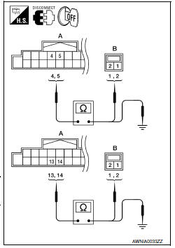
- Disconnect AV control unit connector M115 (A) and suspect speaker connector.
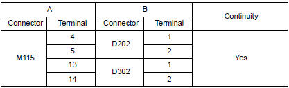
- Check continuity between AV control unit harness connector M115 (A) and suspect speaker harness connector (B).
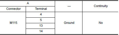
- Check continuity between AV control unit harness connector M115 (A) and ground.
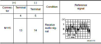
3.REAR DOOR SPEAKER SIGNAL CHECK
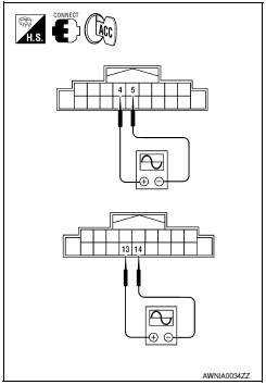
- Connect AV control unit connector and rear door speaker connector.
- Turn ignition switch to ACC.
- Push POWER switch.
- Check the signal between AV control unit harness connector terminals with CONSULT or oscilloscope.
 Tweeter
Description
The AV control unit sends audio signals to the tweeters using the front door
speaker circuits.
Diagnosis Procedure
1.CONNECTOR CHECK
Check the AV control unit and speaker connectors ...
 Subwoofer
Description
The AV control unit sends audio signals to the subwoofer amp. The subwoofer
amp. amplifies the audio signals before sending them to the subwoofers using
the audio signal circuits.
Di ...
Other materials:
P1615 diffrence of key
Description
Performs ID verification through BCM and Intelligent Key
when push-button ignition switch is pressed.
Prohibits the start of engine when an unregistered ID of Intelligent Key is
used.
DTC Logic
DTC DETECTION LOGIC
DTC CONFIRMATION PROCEDURE
1.PERFORM DTC CONFIRMATION PROCED ...
Cooling fan control
System Diagram
System Description
INPUT/OUTPUT SIGNAL CHART
*1: The ECM determines the start signal status by the signals of engine speed
and battery voltage.
*2: This signal is sent to ECM via the CAN communication line.
SYSTEM DESCRIPTION
The ECM controls the cooling fan correspon ...
Heated seat
Wiring Diagram
...
Nissan Maxima Owners Manual
- Illustrated table of contents
- Safety-Seats, seat belts and supplemental restraint system
- Instruments and controls
- Pre-driving checks and adjustments
- Monitor, climate, audio, phone and voice recognition systems
- Starting and driving
- In case of emergency
- Appearance and care
- Do-it-yourself
- Maintenance and schedules
- Technical and consumer information
Nissan Maxima Service and Repair Manual

0.0067