Nissan Maxima Service and Repair Manual: Ducts and grilles
Exploded View
Ducts
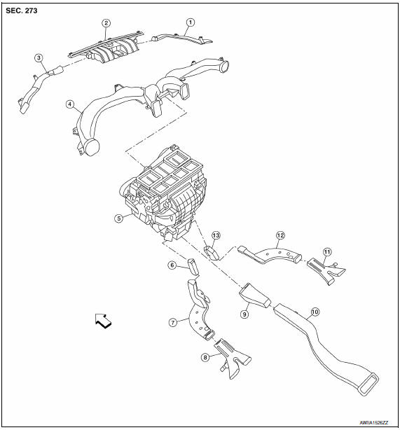
- Side defroster nozzle (RH)
- Front defroster nozzle
- Side defroster nozzle (LH)
- Upper ventilator duct
- Heater and cooling unit assembly
- Connector duct (LH)
- Floor ventilator duct (LH)
- Rear floor duct (LH)
- Connector duct (center)
- Rear ventilator duct (center)
- Rear floor duct (RH)
- Floor ventilator duct (RH)
- Connector duct (RH)
 Front
Front
Grilles
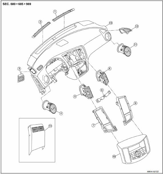
- Front defroster grille (RH)
- Front defroster grille (LH)
- Side defroster grille (LH)
- Side ventilator grille (LH)
- Center ventilator grille (LH)
- Center ventilator grille (RH)
- Center ventilator grille finisher (LH)
- Cluster lid D support
- Center ventilator grille finisher (RH)
- Cluster lid D
- Side ventilator grille (RH)
- Side defroster grille (RH)
- Instrument panel 1
- Rear ventilator grille (part of rear console finisher)
FRONT DEFROSTER NOZZLE
FRONT DEFROSTER NOZZLE : Removal and Installation
REMOVAL
CAUTION: Before servicing, turn the ignition switch off, disconnect both battery terminals and wait at least three minutes.
- Disconnect the battery negative and positive terminals.
- Remove the instrument panel. Refer to IP-11, "Removal and Installation".
- Remove the front defroster nozzle.
INSTALLATION
Installation is in the reverse order of removal.
UPPER VENTILATOR DUCT
UPPER VENTILATOR DUCT : Removal and Installation
REMOVAL
CAUTION: Before servicing, turn the ignition switch off, disconnect both battery terminals and wait at least three minutes.
- Disconnect the battery negative and positive terminals. Refer to PG-67, "Removal and Installation (Battery)".
- Remove the instrument panel. Refer to IP-11, "Removal and Installation".
- Remove the upper ventilator duct.
INSTALLATION
Installation is in the reverse order of removal.
SIDE DEFROSTER NOZZLE
SIDE DEFROSTER NOZZLE : Removal and Installation
REMOVAL
CAUTION: Before servicing, turn the ignition switch off, disconnect both battery terminals and wait at least three minutes.
- Disconnect the battery negative and positive terminals. Refer to PG-67, "Removal and Installation (Battery)".
- Remove the instrument panel. Refer to IP-11, "Removal and Installation".
- Remove the front defroster nozzle.
- Remove the side defroster nozzle (LH/RH).
INSTALLATION
Installation is in the reverse order of removal.
REAR FLOOR DUCTS
REAR FLOOR DUCTS : Removal and Installation
REAR FLOOR DUCT (LH/RH)
Removal
- Remove the rear ventilator duct (center). Refer to VTL-12, "REAR VENTILATOR DUCTS : Removal and Installation".
- Remove the rear floor duct (LH/RH) clips.
- Remove the rear floor ducts (LH/RH).
Installation
Installation is in the reverse order of removal.
FLOOR VENTILATOR DUCT (LH/RH)
Removal
- Remove the connector duct. Refer to VTL-11, "REAR FLOOR DUCTS : Removal and Installation".
- Remove the rear ventilator duct (LH/RH) clips.
- Remove the rear ventilator ducts (LH/RH).
Installation
Installation is in the reverse order of removal.
CONNECTOR DUCT
Removal
- Remove the center console. Refer to IP-14, "Removal and Installation".
- Remove the connector duct (LH/RH).
Installation
Installation is in the reverse order of removal.
REAR VENTILATOR DUCTS
REAR VENTILATOR DUCTS : Removal and Installation
CONNECTOR DUCT (CENTER)
Removal
- Remove the center console. Refer to IP-14, "Removal and Installation".
- Remove the rear ventilator duct (center).
- Remove the connector duct (center).
Installation
Installation is in the reverse order of removal.
REAR VENTILATOR DUCT (CENTER)
Removal
- Remove the center console. Refer to IP-14, "Removal and Installation".
- Remove the rear ventilator duct (center).
Installation
Installation is in the reverse order of removal.
FRONT DEFROSTER GRILLE
FRONT DEFROSTER GRILLE : Removal and Installation
REMOVAL
Remove the front defroster grille from the instrument panel.
CAUTION: Use a suitable tool to remove the grille to avoid damage to the instrument panel.
INSTALLATION
Installation is in the reverse order of removal.
CENTER VENTILATOR GRILLES
CENTER VENTILATOR GRILLES : Removal and Installation
REMOVAL
- Remove cluster lid D. Refer to IP-18, "Removal and Installation".
- Remove the A/C switch assembly or the multifunction switch from cluster lid D.
- Remove the cluster lid D support.
- Remove the center ventilator grilles with finisher.
- Remove the center ventilator grille from the finisher.
INSTALLATION
Installation is in the reverse order of removal.
SIDE VENTILATOR GRILLES
SIDE VENTILATOR GRILLES : Removal and Installation
NOTE: This procedure should only be used if the side ventilator grille is going to be reused for installation and not replaced with a new one.
REMOVAL
- Remove the instrument panel. Refer to IP-11, "Removal and Installation".
- Remove the upper ventilator duct from the instrument panel.
- Release the clips (A) with a suitable tool and push the side ventilator grille out the front of the instrument panel.
CAUTION: Use care to remove the side ventilator grille so as not to damage the instrument panel.
INSTALLATION
Installation is in the reverse order of removal.
CAUTION: Use care when inserting the side ventilator grille so as not to damage the instrument panel.
SIDE VENTILATOR GRILLES : Replacement
SIDE VENTILATOR GRILLE (RH)
CAUTION: This procedure should only be used when replacing the side ventilator grille (RH) with a new one, as the side ventilator grille will be damaged during removal and cannot be reused.
Removal
- Remove the glove box assembly. Refer to IP-20, "Removal and Installation".
- Depress the LH and RH bottom clips (A) and the LH upper clip
(B) with suitable tools.
CAUTION: Use care when inserting the suitable tool so as not to damage the instrument panel.
- Grip the front of the side ventilator grille with a suitable tool to pull from the front and use your hand to push from behind to remove the side ventilator grille from the instrument panel. Discard the side ventilator grille.
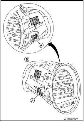
CAUTION:
- The RH upper clip (C) will bend when the side ventilator grille is removed.
- Use care when removing the side ventilator grille so as not to damage the instrument panel.
- The side ventilator grille cannot be reused.
CAUTION: Use care when inserting the new side ventilator grille so as not to damage the instrument panel.
- Insert the new side ventilator grille into the front of the instrument panel. Push the new side ventilator grille in evenly so it does not get cocked to one side.
- Push the new side ventilator grille in until it is flush with the
opening in the front of the instrument panel.
Make sure the side ventilator grille is correctly seated into the upper ventilator duct when fully inserted into the opening in the front of the instrument panel.
SIDE VENTILATOR GRILLE (LH)
CAUTION: This procedure should only be used when replacing the side ventilator grille (LH), as the side ventilator grille will be damaged during removal and cannot be reused.
Removal
- Remove the instrument lower panel LH. Refer to IP-19, "Removal and Installation".
- Depress the LH and RH bottom clips (A) and the RH upper clip (B) with
suitable tools.
CAUTION: Use care when inserting the suitable tool so as not to damage the instrument panel.
- Grip the front of the side ventilator grille with a suitable tool to pull from the front and use your hand to push from behind to remove the side ventilator grille from the instrument panel. Discard the side ventilator grille.
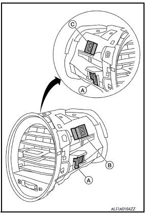
CAUTION:
- The LH upper clip (C) will bend when the side ventilator grille is removed.
- Use care when removing the side ventilator grille so as not to damage the instrument panel.
- The side ventilator grille cannot be reused.
Installation
CAUTION: Use care when inserting the new side ventilator grille so as not to damage the instrument panel.
- Insert the new side ventilator grille into the front of the instrument panel. Push the new side ventilator grille in evenly so it does not get cocked to one side.
- Push the new side ventilator grille in until it is flush with the
opening in the front of the instrument panel.
Make sure the side ventilator grille is correctly seated into the upper ventilator duct when fully inserted into the opening in the front of the instrument panel.
SIDE DEFROSTER GRILLES
SIDE DEFROSTER GRILLES : Removal and Installation
REMOVAL
Remove side defroster grilles from the instrument panel using a suitable tool.
CAUTION: Use a suitable tool to remove the grille to avoid damage to the instrument panel.
INSTALLATION
Installation is in the reverse order of removal.
REAR VENTILATOR GRILLE
REAR VENTILATOR GRILLE : Removal and Installation
REMOVAL
Remove console rear finisher. Refer to IP-10, "Exploded View".
NOTE: The rear ventilator grille is part of the console rear finisher.
INSTALLATION
Installation is in the reverse order of removal.

 Blower unit
BLOWER UNIT
BLOWER UNIT : Removal and Installation
COMPONENTS
Heater and cooling unit
Blower unit Front
REMOVAL
Remove the heater and cooling unit assembly. Refer to HA-47,
"HEA ...
Other materials:
Precautions on child restraints
WARNING
Failure to follow the warnings and instructions
for proper use and installation
of child restraints could result in
serious injury or death of a child or
other passengers in a sudden stop or
collision:
The child restraint must be used and
installed properly. Always follow all ...
Body sealing
Description
The following figure shows the areas which are sealed at the factory. Sealant
which has been applied to these
areas should be smooth and free from cuts or gaps. Care should be taken not to
apply an excess amount of
sealant and not to allow other unaffected parts to come into con ...
Headlamp aiming adjustment
Description
PREPARATION BEFORE ADJUSTING
CAUTION: Do not use organic solvent
(thinner, gasoline etc.).
NOTE:
For details, refer to the regulations in your own country.
Perform aiming adjustment if the vehicle front body has been
repaired and/or the headlamp assembly has been replaced.
...
Nissan Maxima Owners Manual
- Illustrated table of contents
- Safety-Seats, seat belts and supplemental restraint system
- Instruments and controls
- Pre-driving checks and adjustments
- Monitor, climate, audio, phone and voice recognition systems
- Starting and driving
- In case of emergency
- Appearance and care
- Do-it-yourself
- Maintenance and schedules
- Technical and consumer information
Nissan Maxima Service and Repair Manual

0.0063