Nissan Maxima Service and Repair Manual: Crash zone sensor
Component
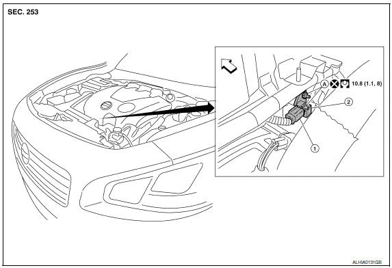
- Crash zone sensor harness connector
- Crash zone sensor
- Nut
 Front
Front
Removal and Installation
CAUTION:
- Before servicing, turn ignition switch OFF, disconnect both battery terminals and wait at least 3 minutes.
- Do not use air tools or electric tools for servicing.
- Replace the crash zone sensor of deployed SRS driver air bag and deployed SRS front passenger air bag.
- Do not cause impact to the crash zone sensor by dropping etc. Replace the crash zone sensor if it has been dropped or sustained an impact.
REMOVAL
- Disconnect the negative and positive battery terminals, then wait at least 3 minutes. Refer to PG-67, "Removal and Installation (Battery)".
- Remove the front air duct, then position upper radiator hose aside.
- Disconnect the harness connector the crash zone sensor.
- Remove the nuts, then remove crash zone sensor.
INSTALLATION
Installation is in the reverse order of removal.
CAUTION:
- Do not use old crash zone sensor nuts after removal; replace with new nuts.
- Be careful not to damage the crash zone sensor harness.
- After the work is completed, make sure no system malfunction is detected by air bag warning lamp.
- In case a malfunction is detected by the air bag warning lamp, reset by the self-diagnosis function and delete the memory by CONSULT.
- If a malfunction is still detected after the above operation,
perform self-diagnosis to repair malfunctions.
Refer to SRC-12, "SRS Operation Check".
 Side air bag module
Removal and Installation
SEAT ASSEMBLY WITH SIDE AIR BAG MODULE
Seatback board
Seatback assembly
Seatback frame
Side air bag module
WARNING: Do not leave any objects
(screwdriver ...
 Side air bag (satellite) sensor
Removal and Installation
CAUTION:
Before servicing, turn ignition switch OFF, disconnect both
battery terminals and wait at least 3 minutes.
Do not use air tools or electric tools for se ...
Other materials:
B2560 starter control relay
Description
Starter control relay, integrated in IPDM E/R, permits
the starter relay operation when in N or P position. It is
installed in parallel with the starter relay.
DTC Logic
DTC DETECTION LOGIC
NOTE:
If DTC B2560 is displayed with DTC
U1000, first perform the trouble diagno ...
Precaution
PRECAUTIONS
Precaution for Supplemental Restraint System (SRS) "AIR BAG" and
"SEAT BELT PRE-TENSIONER"
The Supplemental Restraint System such as "AIR BAG" and "SEAT BELT
PRE-TENSIONER", used along with a front seat belt, helps to reduce the risk
or severity of injury to the driver and front ...
ABS actuator and electric unit (control unit)
Exploded View
From master cylinder secondary side
Grommet
ABS actuator and electric unit (control
unit) bracket
From master cylinder primary side
To front LH brake caliper
To rear RH brake caliper
To rear LH brake caliper
To front RH brake caliper
ABS actuator and el ...
Nissan Maxima Owners Manual
- Illustrated table of contents
- Safety-Seats, seat belts and supplemental restraint system
- Instruments and controls
- Pre-driving checks and adjustments
- Monitor, climate, audio, phone and voice recognition systems
- Starting and driving
- In case of emergency
- Appearance and care
- Do-it-yourself
- Maintenance and schedules
- Technical and consumer information
Nissan Maxima Service and Repair Manual

0.0056