Nissan Maxima Service and Repair Manual: Side air bag (satellite) sensor
Removal and Installation
CAUTION:
- Before servicing, turn ignition switch OFF, disconnect both battery terminals and wait at least 3 minutes.
- Do not use air tools or electric tools for servicing.
- Replace the satellite sensor of deployed SRS front side air bag and deployed SRS side curtain air bag.
- Do not cause impact to the side air bag (satellite) sensor by dropping etc. Replace the side air bag (satellite) sensor if it has been dropped or sustained an impact.
REMOVAL
- Disconnect the negative and positive battery terminals, then wait at least 3 minutes. Refer to PG-67, "Removal and Installation (Battery)".
- Remove the front seat belt retractor. Refer to SB-6, "Removal and Installation".
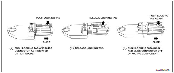
- Disconnect the harness connector from the side air bag (satellite) sensor slide double locking. Refer to SRC-9, "SRS Component Connectors".
- Remove the nuts (A), then remove side air bag (satellite) sensor (2)
from center pillar (1) studs.
 : Front
(3): Side air bag (satellite) sensor slide double locking harness connector.
INSTALLATION
Installation is in the reverse order of removal.
CAUTION:
- Do not use old nuts after removal; replace with new nuts.
- Be careful not to damage the satellite sensor harness.
- After the work is completed, make sure no system malfunction is detected by air bag warning lamp.
- In case a malfunction is detected by the air bag warning lamp, reset by the self-diagnosis function and delete the memory by CONSULT.
- If a malfunction is still detected after the above operation,
perform self-diagnosis to repair malfunctions.
Refer to SRC-12, "SRS Operation Check".
 Crash zone sensor
Component
Crash zone sensor harness connector
Crash zone sensor
Nut
Front
Removal and Installation
CAUTION:
Before servicing, turn ignition switch OFF, disconnect both
bat ...
 Diagnosis sensor unit
Removal and Installation
WARNING:
Before servicing, turn ignition switch OFF, disconnect both
battery terminals and wait at least 3 minutes.
Before disconnecting the air bag sensor unit harn ...
Other materials:
Hands-free phone system
System Diagram
System Description
Refer to the Owner's Manual for Bluetooth telephone system operating
instructions.
NOTE: Cellular telephones must have their
wireless connection set up (paired) before using the Bluetooth telephone
system.
Bluetooth telephone system allows users who have ...
Power supply and ground circuit
CLIMATE CONTROLLED SEAT CONTROL UNIT
CLIMATE CONTROLLED SEAT CONTROL UNIT : Diagnosis Procedure
Regarding Wiring Diagram information, refer to SE-44, "Wiring Diagram".
1.CHECK FUSES
2.CHECK BATTERY POWER SUPPLY CIRCUIT
Turn ignition switch OFF.
Disconnect climate controlled seat control ...
Shift lock system
System Diagram
System Description
The selector lever cannot be shifted from "P" position to any other position
unless the ignition switch is in the
ON position and the brake pedal is depressed.
Component Parts Location
BCM (view with combination meter
removed)
Stop la ...
Nissan Maxima Owners Manual
- Illustrated table of contents
- Safety-Seats, seat belts and supplemental restraint system
- Instruments and controls
- Pre-driving checks and adjustments
- Monitor, climate, audio, phone and voice recognition systems
- Starting and driving
- In case of emergency
- Appearance and care
- Do-it-yourself
- Maintenance and schedules
- Technical and consumer information
Nissan Maxima Service and Repair Manual

0.007