Nissan Maxima Service and Repair Manual: Diagnosis sensor unit
Removal and Installation
WARNING:
- Before servicing, turn ignition switch OFF, disconnect both battery terminals and wait at least 3 minutes.
- Before disconnecting the air bag sensor unit harness connector, be sure to disconnect the harness connector of each air bag module and pre-tensioner seat belt to prevent air bag deployment by static electricity.
- Do not use air tools or electric tools for servicing.
- When replacing the air bag diagnosis sensor unit, always check with the parts department for the latest parts information. Installing an incorrect air bag diagnosis sensor unit may or may not cause the air bag warning lamp to illuminate and may cause incorrect deployment of the supplemental air bags and seat belt pre-tensioner in a collision resulting in serious personal injury or death.
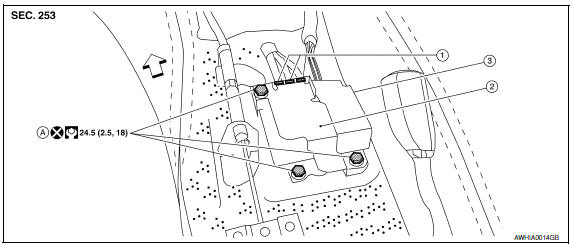
REMOVAL
- Diagnosis sensor unit harness connector
- Diagnosis sensor unit shield
- Diagnosis sensor unit
- Diagnosis sensor unit bolts
 Front
Front
- Always check the air bag diagnosis sensor unit ECU discriminated number (identification number) or part number using CONSULT.
- Disconnect the negative and positive battery terminals, then wait at least 3 minutes. Refer to PG-67, "Removal and Installation (Battery)".
- Disconnect the harness connectors for each of the following SRS components. Refer to SR-19, "Removal and Installation" (Side curtain air bag module), SE-68, "Removal and Installation" (Side air bag module with climate controlled seats) or SE-126, "Removal and Installation" (Side air bag module without climate controlled seats), SB-6, "Removal and Installation" (Seat belt pre-tensioner).
- Remove the center console. Refer to IP-21, "Disassembly and Assembly".
- Disconnect the harness connectors from the diagnosis sensor unit.
- Remove the bolts, then remove the diagnosis sensor unit.
CAUTION:
- Do not impact the air bag diagnosis sensor unit.
- Do not cause an impact to the diagnosis sensor unit by dropping etc. Replace the diagnosis sensor unit if it has been dropped or sustained an impact.
INSTALLATION
Installation is in the reverse order of removal.
CAUTION:
- Do not use old bolts after removal; replace with new bolts.
- Be careful not to damage the diagnosis sensor unit harness.
- After the work is completed, make sure no system malfunction is detected by air bag warning lamp.
- In case a malfunction is detected by the air bag warning lamp, reset by the self-diagnosis function and delete the memory by CONSULT.
- - If a malfunction is still detected after the above operation,
perform self-diagnosis to repair malfunctions.
Refer to SRC-12, "SRS Operation Check".
- After replacing the air bag diagnosis sensor unit, confirm using CONSULT that the ECU discriminated number (identification number) or part number of the new replacement air bag diagnosis sensor unit matches the ECU discriminated number (identification number) or part number of the replaced (old) air bag diagnosis sensor unit.
NOTE: If the ECU discriminated number or part number of the new replacement air bag diagnosis sensor unit differs from the ECU discriminated number or part number of the replaced air bag diagnosis sensor unit, reconfirm the parts information and verify that the correct air bag diagnosis sensor unit was installed.
 Side air bag (satellite) sensor
Removal and Installation
CAUTION:
Before servicing, turn ignition switch OFF, disconnect both
battery terminals and wait at least 3 minutes.
Do not use air tools or electric tools for se ...
 Occupant classification system control unit
Removal and Installation
Removal and Installation
The occupant classification system control unit and sensor mat are an
integral part of the front passenger seat cushion, and are replaced as an
...
Other materials:
Front wiper does not operate
Description
The front wiper does not operate under any operation conditions
Diagnosis Procedure
1. CHECK WIPER RELAY OPERATION
IPDM E/R AUTO ACTIVE TEST
Start IPDM E/R auto active test. Refer to PCS-11, "Diagnosis
Description".
Check that the front wiper operates at the LO/HI operation. ...
Wiring diagram
SRS AIR BAG CONTROL SYSTEM
Wiring Diagram - For Mexico
Wiring Diagram - Except Mexico
...
Three-way catalyst
The three-way catalyst is an emission control
device installed in the exhaust system. Exhaust
gases in the three-way catalyst are burned at
high temperatures to help reduce pollutants.
WARNING
The exhaust gas and the exhaust system
are very hot. Keep people, animals
or flammable material ...
Nissan Maxima Owners Manual
- Illustrated table of contents
- Safety-Seats, seat belts and supplemental restraint system
- Instruments and controls
- Pre-driving checks and adjustments
- Monitor, climate, audio, phone and voice recognition systems
- Starting and driving
- In case of emergency
- Appearance and care
- Do-it-yourself
- Maintenance and schedules
- Technical and consumer information
Nissan Maxima Service and Repair Manual

0.0081