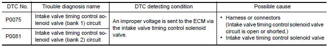
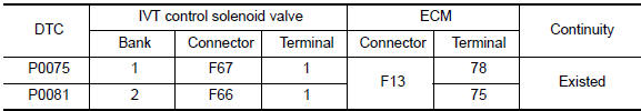
Nissan Maxima Service and Repair Manual: P0075, P0081 IVT control solenoid valve
Description
Intake valve timing control solenoid valve is activated by ON/OFF pulse duty (ratio) signals from the ECM.
The intake valve timing control solenoid valve changes the oil amount and direction of flow via the intake valve timing control unit or stops oil flow.
The longer pulse width advances valve angle.
The shorter pulse width retards valve angle.
When ON and OFF pulse widths become equal, the solenoid valve stops oil pressure flow to fix the intake valve angle at the control position.
DTC Logic
DTC DETECTION LOGIC
DTC CONFIRMATION PROCEDURE
1.PRECONDITIONING
If DTC Confirmation Procedure has been previously conducted, always perform the following before conducting the next test.
- Turn ignition switch OFF and wait at least 10 seconds.
- Turn ignition switch ON.
- Turn ignition switch OFF and wait at least 10 seconds.
2.PERFORM DTC CONFIRMATION PROCEDURE
- Start engine and let it idle for 5 seconds.
- Check 1st trip DTC.
Diagnosis Procedure
Regarding Wiring Diagram information
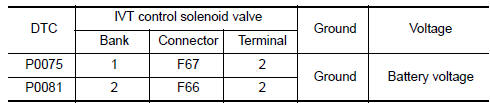
1.CHECK INTAKE VALVE TIMING CONTROL SOLENOID VALVE POWER SUPPLY CIRCUIT\
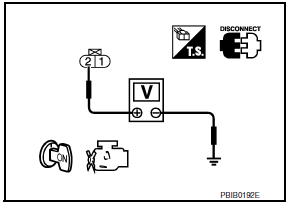
- Turn ignition switch OFF.
- Disconnect intake valve timing control solenoid valve harness connector.
- Turn ignition switch ON.
- Check the voltage between intake valve timing (IVT) control solenoid valve harness connector and ground with CONSULT or tester.
2.CHECK INTAKE VALVE TIMING CONTROL SOLENOID VALVE OUTPUT SIGNAL CIRCUIT FOR OPEN AND SHORT
- Turn ignition switch OFF.
- Disconnect ECM harness connector.
- Check the continuity between intake valve timing control solenoid valve harness connector and ECM harness connector.
- Also check harness for short to ground and short to power.
3.CHECK INTAKE VALVE TIMING CONTROL SOLENOID VALVE
4.CHECK INTERMITTENT INCIDENT
Component Inspection
1.CHECK INTAKE VALVE TIMING CONTROL SOLENOID VALVE-I
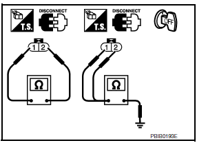
- Disconnect intake valve timing control solenoid valve harness connector.
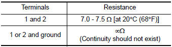
- Check resistance between intake valve timing control solenoid valve terminals as per the following.
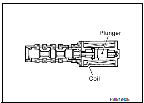
2.CHECK INTAKE VALVE TIMING CONTROL SOLENOID VALVE-II
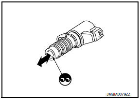
- Remove intake valve timing control solenoid valve. Refer to EM-54, "Exploded View".
- Provide 12 V DC between intake valve timing control solenoid valve terminals 1 and 2, and then interrupt it. Check that the plunger moves as shown in the figure.
CAUTION: Never apply 12 V DC continuously for 5 seconds or more.
Doing so may result in damage to the coil in intake valve timing control solenoid valve.
NOTE: Always replace O-ring when intake valve timing control solenoid valve is removed.
 P0037, P0038, P0057, P0058 HO2S2 heater
Description
SYSTEM DESCRIPTION
The ECM performs ON/OFF control of the heated oxygen sensor 2 heater
corresponding to the engine speed,
amount of intake air and engine coolant temperature.
O ...
 P0078, P0084 EVT control magnet retarder
Description
Exhaust valve timing control magnet retarder (1) controls the shut/
open timing of the exhaust valve by ON/OFF pulse duty signals sent
from the ECM.
The longer pulse width reta ...
Other materials:
Power generation voltage variable control system
System Diagram
System Description
Power generation variable voltage control system has been adopted. By varying
the voltage to the generator,
engine load due to power generation of the generator is reduced and fuel
consumption is decreased.
NOTE:
When any malfunction is detected in th ...
Insufficient heating
Component Function Check
Symptom
Insufficient heating
No warm air comes out. (Airflow volume is normal.)
INSPECTION FLOW
1. CONFIRM SYMPTOM BY PERFORMING OPERATION CHECK - TEMPERATURE INCREASE
Press the AUTO switch.
Turn temperature control dial (driver side) clockwise until 32C
...
Diagnosis and repair workflow
Work Flow
OVERALL SEQUENCE
DETAILED FLOW
1. GET INFORMATION FOR SYMPTOM
Get the detailed information from the customer about the symptom (the
condition and the environment when
the incident/malfunction occurred).
2. CHECK DTC
Check DTC.
Perform the following procedure if DTC is ...
Nissan Maxima Owners Manual
- Illustrated table of contents
- Safety-Seats, seat belts and supplemental restraint system
- Instruments and controls
- Pre-driving checks and adjustments
- Monitor, climate, audio, phone and voice recognition systems
- Starting and driving
- In case of emergency
- Appearance and care
- Do-it-yourself
- Maintenance and schedules
- Technical and consumer information
Nissan Maxima Service and Repair Manual

0.0054