
Nissan Maxima Service and Repair Manual: P0037, P0038, P0057, P0058 HO2S2 heater
Description
SYSTEM DESCRIPTION

The ECM performs ON/OFF control of the heated oxygen sensor 2 heater corresponding to the engine speed, amount of intake air and engine coolant temperature.
OPERATION

DTC Logic
DTC DETECTION LOGIC
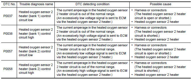
DTC CONFIRMATION PROCEDURE
1.PRECONDITIONING
If DTC Confirmation Procedure has been previously conducted, always perform the following before conducting the next test.
- Turn ignition switch OFF and wait at least 10 seconds.
- Turn ignition switch ON.
- Turn ignition switch OFF and wait at least 10 seconds.
TESTING CONDITION: Before performing the following procedure, confirm that battery voltage is between 11 V at idle.
2.PERFORM DTC CONFIRMATION PROCEDURE
With CONSULT
- Turn ignition switch ON and select "DATA MONITOR" mode with CONSULT.
- Start engine and warm it up to the normal operating temperature.
- Turn ignition switch OFF and wait at least 10 seconds.
- Turn ignition switch ON.
- Turn ignition switch OFF and wait at least 10 seconds.
- Start engine and keep the engine speed between 3,500 and 4,000 rpm for at least 1 minute under no load.
- Let engine idle for 1 minute.
- Check 1st trip DTC.
With GST
Follow the procedure "With CONSULT" above.
Diagnosis Procedure
1.CHECK GROUND CONNECTION
- Turn ignition switch OFF.
- Check ground connection E9.
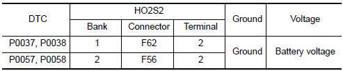
2.CHECK HO2S2 POWER SUPPLY CIRCUIT
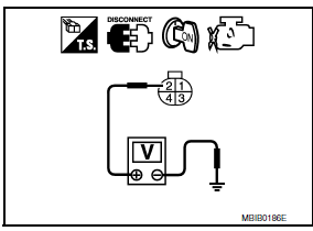
- Disconnect heated oxygen sensor 2 (HO2S2) harness connector.
- Turn ignition switch ON.
- Check the voltage between HO2S2 harness connector and ground.
3.DETECT MALFUNCTIONING PART
Check the following.
- IPDM E/R connector F10
- 15 A fuse (No. 37)
- Harness for open or short between heated oxygen sensor 2 and fuse
4.CHECK HO2S2 OUTPUT SIGNAL CIRCUIT FOR OPEN AND SHORT
- Turn ignition switch OFF.
- Disconnect ECM harness connector.
- Check the continuity between HO2S2 harness connector and ECM harness connector.
- Also check harness for short to ground and short to power.

5.CHECK HEATED OXYGEN SENSOR 2 HEATER
6.REPLACE HEATED OXYGEN SENSOR 2
Replace malfunctioning heated oxygen sensor 2.
CAUTION:
- Discard any heated oxygen sensor which has been dropped from a height of more than 0.5 m (19.7 in) onto a hard surface such as a concrete floor; use a new one.
- Before installing new oxygen sensor, clean exhaust system threads using Oxygen Sensor Thread Cleaner [commercial service tool (J-43897-18 or J-43897-12)] and approved anti-seize lubricant (commercial service tool).
7.CHECK INTERMITTENT INCIDENT
Component Inspection
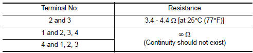
1.CHECK HEATED OXYGEN SENSOR 2 HEATER
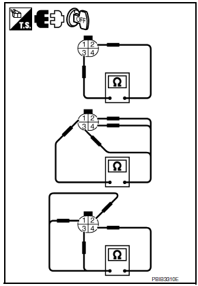
Check resistance between HO2S2 terminals as per the following.
2.REPLACE HEATED OXYGEN SENSOR 2
CAUTION:
- Discard any heated oxygen sensor which has been dropped from a height of more than 0.5 m (19.7 in) onto a hard surface such as a concrete floor; use a new one.
- Before installing new oxygen sensor, clean exhaust system threads using Oxygen Sensor Thread Cleaner [commercial service tool (J-43897-18 or J-43897-12)] and approved anti-seize lubricant (commercial service tool).
 P0031, P0032, P0051, P0052 A/F sensor 1 heater
Description
SYSTEM DESCRIPTION
The ECM performs ON/OFF duty control of the A/F sensor 1 heater corresponding
to the engine operating
condition to keep the temperature of A/F sensor 1 element ...
 P0075, P0081 IVT control solenoid valve
Description
Intake valve timing control solenoid valve is activated by ON/OFF
pulse duty (ratio) signals from the ECM.
The intake valve timing control solenoid valve changes the oil
amount ...
Other materials:
RGB AREA (YS) signal circuit
Description
Transmits the display area of RGB image displayed by AV control unit with RGB
area (YS) signal to display unit.
Diagnosis Procedure
1.CHECK CONTINUITY RGB AREA (YS) SIGNAL CIRCUIT
Turn ignition switch OFF.
Disconnect display unit connector M141 and AV control unit
conne ...
Exterior rear
Rear window defroster switch
High-mounted stop light
Interior trunk lid release. Trunk lid
Exterior trunk lid release/request button. Rearview camera
Rear sonar sensors (if so equipped)
Replacing bulbs
Fuel-filler door. Fuel recommendation
Child safety rear door locks
R ...
Squeak and rattle trouble diagnoses
Work Flow
CUSTOMER INTERVIEW
Interview the customer if possible, to determine the conditions that exist
when the noise occurs. Use the Diagnostic
Worksheet during the interview to document the facts and conditions when the
noise occurs and any
customer's comments; refer to DLK-199, " ...
Nissan Maxima Owners Manual
- Illustrated table of contents
- Safety-Seats, seat belts and supplemental restraint system
- Instruments and controls
- Pre-driving checks and adjustments
- Monitor, climate, audio, phone and voice recognition systems
- Starting and driving
- In case of emergency
- Appearance and care
- Do-it-yourself
- Maintenance and schedules
- Technical and consumer information
Nissan Maxima Service and Repair Manual

0.0086