
Nissan Maxima Service and Repair Manual: P0078, P0084 EVT control magnet retarder
Description
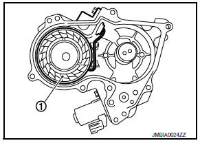
Exhaust valve timing control magnet retarder (1) controls the shut/ open timing of the exhaust valve by ON/OFF pulse duty signals sent from the ECM.
The longer pulse width retards valve timing.
The shorter pulse width advances valve timing.
DTC Logic
DTC DETECTION LOGIC

DTC CONFIRMATION PROCEDURE
1.PRECONDITIONING
If DTC Confirmation Procedure has been previously conducted, always perform the following procedure before conducting the next test.
- Turn ignition switch OFF and wait at least 10 seconds.
- Turn ignition switch ON.
- Turn ignition switch OFF and wait at least 10 seconds.
2.PERFORM DTC CONFIRMATION PROCEDURE
- Start engine and let it idle for 5 seconds.
- Check 1st trip DTC.
Diagnosis Procedure
Regarding Wiring Diagram information
1.CHECK EXHAUST VALVE TIMING (EVT) CONTROL MAGNET RETARDER POWER SUPPLY CIRCUIT
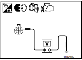
- Turn ignition switch OFF.
- Disconnect EVT control magnet retarder harness connector.
- Turn ignition switch ON.
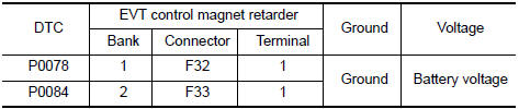
- Check the voltage between EVT control magnet retarder harness connector and ground.
2.CHECK EVT CONTROL MAGNET RETARDER OUTPUT SIGNAL CIRCUIT FOR OPEN AND SHORT
- Turn ignition switch OFF.
- Disconnect ECM harness connector.
- Check the continuity between EVT control magnet retarder harness connector and ECM harness connector.
- Also check harness for short to ground and short to power.

3.CHECK EVT CONTROL MAGNET RETARDER
4.REPLACE EVT CONTROL MAGNET RETARDER
- Replace malfunctioning EVT control magnet retarder
5.CHECK INTERMITTENT INCIDENT
Component Inspection
1.CHECK EXHAUST VALVE TIMING CONTROL MAGNET RETARDER
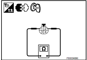
- Turn ignition switch OFF.
- Disconnect exhaust valve timing control magnet retarder harness connector.
- Check resistance between exhaust valve timing control magnet retarder terminals as per the following.

2.REPLACE EXHAUST VALVE TIMING CONTROL MAGNET RETARDER
- Replace malfunctioning exhaust valve timing control magnet retarder
 P0075, P0081 IVT control solenoid valve
Description
Intake valve timing control solenoid valve is activated by ON/OFF
pulse duty (ratio) signals from the ECM.
The intake valve timing control solenoid valve changes the oil
amount ...
 P0101 MAF sensor
Description
The mass air flow sensor (1) is placed in the stream of intake air. It
measures the intake flow rate by measuring a part of the entire
intake flow. The mass air flow sensor co ...
Other materials:
Steering wheel
WARNING
Do not adjust the steering wheel while
driving. You could lose control of your
vehicle and cause an accident.
Do not adjust the steering wheel any
closer to you than is necessary for
proper steering operation and comfort.
The driver's air bag inflates with great
force. If ...
B1129 - B1132 side airbag module RH
Description
DTC B1129 - B1132 FRONT RH SIDE AIR BAG MODULE
The front RH side air bag module is wired to the air bag diagnosis sensor
unit. The air bag diagnosis sensorunit will monitor for opens and shorts in
detected lines to the front RH side air bag module.
PART LOCATION
DTC Logic
DTC DE ...
Yaw rate/side/decel G sensor
Exploded View
Yaw rate/side/decel G sensor
Yaw rate/side/decel G sensor harness
connector
Front
Removal and Installation
CAUTION:
Do not drop or strike the yaw rate/side/decel G sensor to
prevent damage.
Do not use power tool to remove the yaw rate/side/decel G s ...
Nissan Maxima Owners Manual
- Illustrated table of contents
- Safety-Seats, seat belts and supplemental restraint system
- Instruments and controls
- Pre-driving checks and adjustments
- Monitor, climate, audio, phone and voice recognition systems
- Starting and driving
- In case of emergency
- Appearance and care
- Do-it-yourself
- Maintenance and schedules
- Technical and consumer information
Nissan Maxima Service and Repair Manual

0.0113