Nissan Maxima Service and Repair Manual: P0101 MAF sensor
Description
The mass air flow sensor (1) is placed in the stream of intake air. It measures the intake flow rate by measuring a part of the entire intake flow. The mass air flow sensor controls the temperature of the hot wire to a certain amount. The heat generated by the hot wire is reduced as the intake air flows around it. The greater air flow, the greater the heat loss.
Therefore, the electric current supplied to hot wire is changed to maintain the temperature of the hot wire as air flow increases. The ECM detects the air flow by means of this current change.
DTC Logic
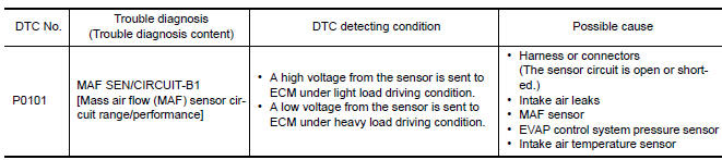
DTC DETECTION LOGIC
NOTE: If DTC P0101 is displayed with other DTC, first perform the trouble diagnosis for other DTC.
DTC CONFIRMATION PROCEDURE
1.PRECONDITIONING
If DTC CONFIRMATION PROCEDURE has been previously conducted, always perform the following procedure before conducting the next test.
- Turn ignition switch OFF and wait at least 10 seconds.
- Turn ignition switch ON.
- Turn ignition switch OFF and wait at least 10 seconds.
2.PERFORM DTC CONFIRMATION PROCEDURE
- Start engine and warm it up to normal operating temperature.
- Drive the vehicle for at least 5 seconds under the following conditions:
CAUTION: Always drive vehicle at safe speed.
NOTE:
- The gear must be fixed while driving the vehicle.
- Keep the accelerator pedal as steady as possible during cruising.
- Check 1st trip DTC.
Diagnosis Procedure
1.CHECK INTAKE SYSTEM
Check the following for connection.
- Air duct
- Vacuum hoses
- Intake air passage between air duct and intake manifold
2.CHECK GROUND CONNECTION
- Turn ignition switch OFF.
- Check ground connection E9.
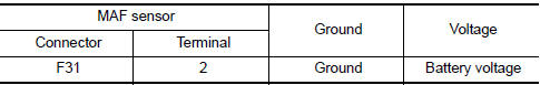
3.CHECK MASS AIR FLOW (MAF) SENSOR POWER SUPPLY CIRCUIT
- Disconnect MAF sensor harness connector.
- Turn ignition switch ON.
- Check the voltage between MAF sensor harness connector and ground.
4.DETECT MALFUNCTIONING PART
Check the following.
- Harness connectors E11, F2
- Junction block connectors E44, E45
- Harness for open or short between mass air flow sensor and ECM
- Harness for open or short between mass air flow sensor and IPDM E/R
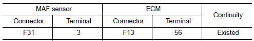
5.CHECK MAF SENSOR GROUND CIRCUIT FOR OPEN AND SHORT
- Turn ignition switch OFF.
- Disconnect ECM harness connector.
- Check the continuity between MAF sensor harness connector and ECM harness connector.
- Also check harness for short to ground and short to power.
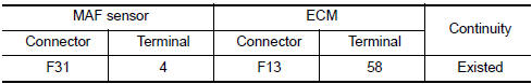
6.CHECK MAF SENSOR INPUT SIGNAL CIRCUIT FOR OPEN AND SHORT
- Check the continuity between MAF sensor harness connector and ECM harness connector.
- Also check harness for short to ground and short to power
7.CHECK INTAKE AIR TEMPERATURE SENSOR
Check intake air temperature sensor.
8.CHECK EVAP CONTROL SYSTEM PRESSURE SENSOR
Check EVAP control system pressure sensor.
9.CHECK MAF SENSOR
Check MAF sensor
10.CHECK INTERMITTENT INCIDENT
Check intermittent incident
Component Inspection
1.CHECK MASS AIR FLOW SENSOR-I
With CONSULT
- Reconnect all harness connectors disconnected.
- Start engine and warm it up to normal operating temperature.
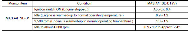
- Connect CONSULT and select "DATA MONITOR" mode.
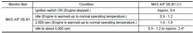
- Select "MAS A/F SE-B1" and check indication under the following conditions.
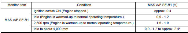
*: Check for linear voltage rise in response to engine being increased to about 4,000 rpm.
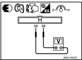
- Without CONSULT Reconnect all harness connectors disconnected.
- Start engine and warm it up to normal operating temperature.
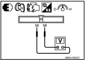
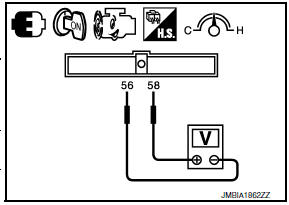
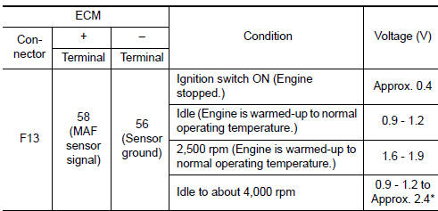
- Check the voltage between ECM harness connector terminals under the following conditions.
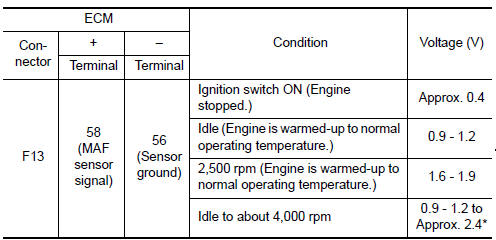
*: Check for linear voltage rise in response to engine being increased to about 4,000 rpm.
2.CHECK FOR THE CAUSE OF UNEVEN AIR FLOW VIA THE MASS AIR FLOW SENSOR
Check for the cause of uneven air flow via the mass air flow sensor. Refer to the following.
- Crushed air ducts
- Malfunctioning seal of air cleaner element
- Uneven dirt of air cleaner element
- Improper specification of intake air system parts
3.CHECK MASS AIR FLOW SENSOR-II
With CONSULT
- Repair or replace malfunctioning part.
- Start engine and warm it up to normal operating temperature.
- Connect CONSULT and select "DATA MONITOR" mode.
- Select "MAS A/F SE-B1" and check indication under the following conditions.
*: Check for linear voltage rise in response to engine being increased to about 4,000 rpm.
Without CONSULT
- Repair or replace malfunctioning part.
- Start engine and warm it up to normal operating temperature.
- Check the voltage between ECM harness connector terminals under the following conditions
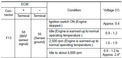
*: Check for linear voltage rise in response to engine being increased to about 4,000 rpm.
4.CHECK MASS AIR FLOW SENSOR-III
With CONSULT
- Turn ignition switch OFF.
- Disconnect mass air flow sensor harness connector and reconnect it again.
- Start engine and warm it up to normal operating temperature.
- Connect CONSULT and select "DATA MONITOR" mode.
- Select "MAS A/F SE-B1" and check indication under the following conditions.
*: Check for linear voltage rise in response to engine being increased to about 4,000 rpm.
Without CONSULT
- Turn ignition switch OFF.
- Disconnect mass air flow sensor harness connector and reconnect it again.
- Start engine and warm it up to normal operating temperature.
- Check the voltage between ECM harness connector terminals under the following conditions.
*: Check for linear voltage rise in response to engine being increased to about 4,000 rpm
 P0078, P0084 EVT control magnet retarder
Description
Exhaust valve timing control magnet retarder (1) controls the shut/
open timing of the exhaust valve by ON/OFF pulse duty signals sent
from the ECM.
The longer pulse width reta ...
 P0102, P0103 MAF sensor
Description
The mass air flow sensor (1) is placed in the stream of intake air. It
measures the intake flow rate by measuring a part of the entire
intake flow. The mass air flow sensor contro ...
Other materials:
Blocking wheels
A. Blocks
B. Flat tire
Place suitable blocks at both the front and back
of the wheel diagonally opposite the flat tire to
prevent the vehicle from moving when it is jacked
up.
WARNING
Be sure to block the wheel as the vehicle
may move and result in personal injury.
Getting the spare tir ...
Clip list
Descriptions for Clips
Replace any clips which are damaged during removal or installation
...
Sound signal circuit
SATELLITE RADIO TUNER
SATELLITE RADIO TUNER : Description
Left and right channel audio signals are supplied from the satellite radio
tuner to the AV control unit through
the sound signal circuits.
SATELLITE RADIO TUNER : Diagnosis Procedure
LEFT CHANNEL
1.CHECK HARNESS
Turn ignition ...
Nissan Maxima Owners Manual
- Illustrated table of contents
- Safety-Seats, seat belts and supplemental restraint system
- Instruments and controls
- Pre-driving checks and adjustments
- Monitor, climate, audio, phone and voice recognition systems
- Starting and driving
- In case of emergency
- Appearance and care
- Do-it-yourself
- Maintenance and schedules
- Technical and consumer information
Nissan Maxima Service and Repair Manual

0.007