Nissan Maxima Service and Repair Manual: P0102, P0103 MAF sensor
Description
The mass air flow sensor (1) is placed in the stream of intake air. It measures the intake flow rate by measuring a part of the entire intake flow. The mass air flow sensor controls the temperature of the hot wire to a certain amount. The heat generated by the hot wire is reduced as the intake air flows around it. The greater air flow, the greater the heat loss.
Therefore, the electric current supplied to hot wire is changed to maintain the temperature of the hot wire as air flow increases. The ECM detects the air flow by means of this current change.
DTC Logic
DTC DETECTION LOGIC
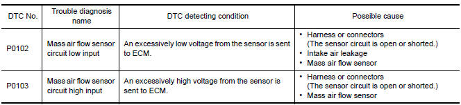
DTC CONFIRMATION PROCEDURE
1.PRECONDITIONING
If DTC Confirmation Procedure has been previously conducted, always perform the following before conducting the next test.
- Turn ignition switch OFF and wait at least 10 seconds.
- Turn ignition switch ON.
- Turn ignition switch OFF and wait at least 10 seconds.
2.PERFORM DTC CONFIRMATION PROCEDURE FOR DTC P0102
- Start engine and wait at least 5 seconds.
- Check DTC.
3.PERFORM DTC CONFIRMATION PROCEDURE FOR DTC P0103-I
- Turn ignition switch ON and wait at least 5 seconds.
- Check DTC.
4.PERFORM DTC CONFIRMATION PROCEDURE FOR DTC P0103-II
- Start engine and wait at least 5 seconds.
- Check DTC.
Diagnosis Procedure
Regarding Wiring Diagram information
1.INSPECTION START
Confirm the detected DTC.
2.CHECK INTAKE SYSTEM
Check the following for connection.
- Air duct
- Vacuum hoses
- Intake air passage between air duct to intake manifold
3.CHECK GROUND CONNECTION
- Turn ignition switch OFF.
- Check ground connection E9.
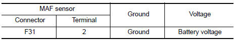
4.CHECK MAF SENSOR POWER SUPPLY CIRCUIT
- Disconnect mass air flow (MAF) sensor harness connector.
- Turn ignition switch ON.
- Check the voltage between MAF sensor harness connector and ground.
5.DETECT MALFUNCTIONING PART
Check the following.
- Harness connectors E11, F2
- Junction block connectors E44, E45
- Harness for open or short between mass air flow sensor and ECM
- Harness for open or short between mass air flow sensor and IPDM E/R
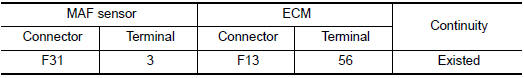
6.CHECK MAF SENSOR GROUND CIRCUIT FOR OPEN AND SHORT
- Turn ignition switch OFF.
- Disconnect ECM harness connector.
- Check the continuity between MAF sensor harness connector and ECM harness connector.
- Also check harness for short to ground and short to power.
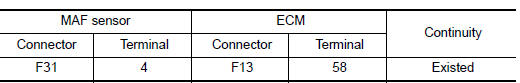
7.CHECK MAF SENSOR INPUT SIGNAL CIRCUIT FOR OPEN AND SHORT
- Check the continuity between MAF sensor harness connector and ECM harness connector.
- Also check harness for short to ground and short to power.
8.CHECK MASS AIR FLOW SENSOR
9.CHECK INTERMITTENT INCIDENT
Component Inspection
1.CHECK MASS AIR FLOW SENSOR-I
With CONSULT
- Reconnect all harness connectors disconnected.
- Start engine and warm it up to normal operating temperature.
- Connect CONSULT and select "DATA MONITOR" mode.
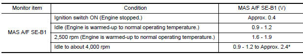
- Select "MAS A/F SE-B1" and check indication under the following conditions
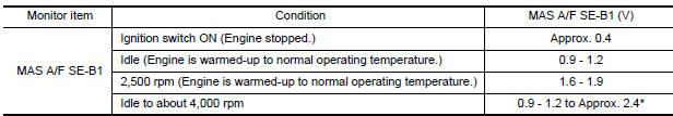
*: Check for linear voltage rise in response to engine being increased to about 4,000 rpm.
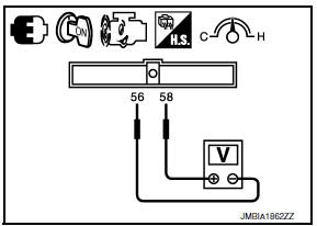
Without CONSULT

- Reconnect all harness connectors disconnected.
- Start engine and warm it up to normal operating temperature.
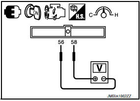
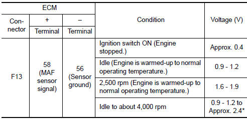
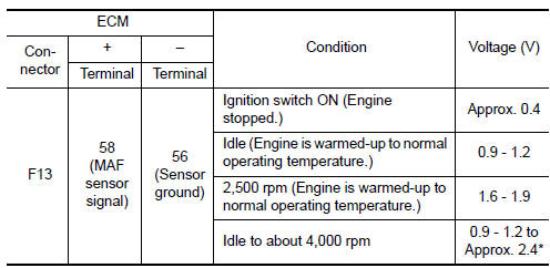
- Check the voltage between ECM harness connector terminals under the following conditions.
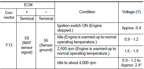
*: Check for linear voltage rise in response to engine being increased to about 4,000 rpm.
2.CHECK FOR THE CAUSE OF UNEVEN AIR FLOW VIA THE MASS AIR FLOW SENSOR
Check for the cause of uneven air flow via the mass air flow sensor. Refer to the following.
- Crushed air ducts
- Malfunctioning seal of air cleaner element
- Uneven dirt of air cleaner element
- Improper specification of intake air system parts
3.CHECK MASS AIR FLOW SENSOR-II
With CONSULT
- Repair or replace malfunctioning part.
- Start engine and warm it up to normal operating temperature.
- Connect CONSULT and select "DATA MONITOR" mode.
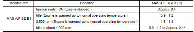
- Select "MAS A/F SE-B1" and check indication under the following conditions.
*: Check for linear voltage rise in response to engine being increased to about 4,000 rpm.
Without CONSULT
- Repair or replace malfunctioning part.
- Start engine and warm it up to normal operating temperature.
- Check the voltage between ECM harness connector terminals under the following conditions.
*: Check for linear voltage rise in response to engine being increased to about 4,000 rpm.
4.CHECK MASS AIR FLOW SENSOR-III
With CONSULT
- Turn ignition switch OFF.
- Disconnect mass air flow sensor harness connector and reconnect it again.
- Start engine and warm it up to normal operating temperature.
- Connect CONSULT and select "DATA MONITOR" mode.
- Select "MAS A/F SE-B1" and check indication under the following conditions.
*: Check for linear voltage rise in response to engine being increased to about 4,000 rpm.
Without CONSULT
- Turn ignition switch OFF.
- Disconnect mass air flow sensor harness connector and reconnect it again.
- Start engine and warm it up to normal operating temperature.
- Check the voltage between ECM harness connector terminals under the following conditions.
*: Check for linear voltage rise in response to engine being increased to about 4,000 rpm.
 P0101 MAF sensor
Description
The mass air flow sensor (1) is placed in the stream of intake air. It
measures the intake flow rate by measuring a part of the entire
intake flow. The mass air flow sensor co ...
 P0111 IAT sensor
Description
The intake air temperature sensor is built-into the mass air flow sensor
(1). The sensor detects intake air temperature and transmits a
signal to the ECM.
The temperature sensi ...
Other materials:
Diagnosis system (BCM)
COMMON ITEM
COMMON ITEM: CONSULT Function (BCM - COMMON ITEM)
APPLICATION ITEM
CONSULT performs the following functions via CAN communication with BCM.
Direct Diagnostic Mode
Description
Ecu Identification
The BCM part number is displayed
Self Diagnostic Re ...
Satellite radio tuner
Reference Value
PHYSICAL VALUES
...
Rear disc brake
Disassembly and Assembly
Union bolt
Brake hose
Copper sealing washer
Cap
Bleed valve
Lower sliding pin bolt
Upper sliding pin bolt
Bushing
Cylinder body
Piston seal
Piston
Piston boot
Retaining ring
Sliding pin boot
Torque member bolt
Washer
Torque m ...
Nissan Maxima Owners Manual
- Illustrated table of contents
- Safety-Seats, seat belts and supplemental restraint system
- Instruments and controls
- Pre-driving checks and adjustments
- Monitor, climate, audio, phone and voice recognition systems
- Starting and driving
- In case of emergency
- Appearance and care
- Do-it-yourself
- Maintenance and schedules
- Technical and consumer information
Nissan Maxima Service and Repair Manual

0.0053