Nissan Maxima Service and Repair Manual: P0111 IAT sensor
Description
The intake air temperature sensor is built-into the mass air flow sensor (1). The sensor detects intake air temperature and transmits a signal to the ECM.
The temperature sensing unit uses a thermistor which is sensitive to the change in temperature. Electrical resistance of the thermistor decreases in response to the rise in temperature.
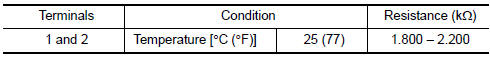
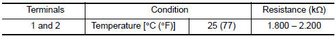
<Reference data>
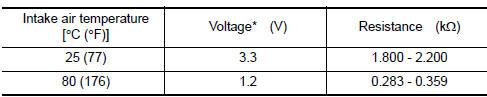
*: These data are reference values and are measured between ECM terminals 50 (Intake air temperature sensor) and 56 (Sensor ground).
DTC Logic
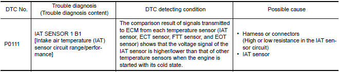
DTC DETECTION LOGIC
DTC CONFIRMATION PROCEDURE
1.INSPECTION START
2.PERFORM COMPONENT FUNCTION CHECK
Perform component function check. Refer to EC-196, "Component Function Check".
NOTE: Use the component function check to check the overall function of the IAT sensor circuit. During this check, a 1st trip DTC might not be confirmed.
3.PRECONDITIONING
If DTC CONFIRMATION PROCEDURE has been previously conducted, always perform the following procedure before conducting the next test.
- Turn ignition switch OFF and wait at least 10 seconds.
- Turn ignition switch ON.
- Turn ignition switch OFF and wait at least 10 seconds.
TESTING CONDITION:
- Before performing the following procedure, do not add fuel.
- Before performing the following procedure, check that fuel level is between 1/4 and 4/4.
- Before performing the following procedure, confirm that battery voltage is 11 V or more at idle.
4.PERFORM DTC CONFIRMATION PROCEDURE
- Start engine and let it idle for 60 minutes.
- . Move the vehicle to a cool place. NOTE: Cool the vehicle in an environment of ambient air temperature between −10C (14F) and 35C (95F).
- Turn ignition switch OFF and soak the vehicle for 12 hours.
CAUTION: Never turn ignition switch ON during soaking.
NOTE: The vehicle must be cooled with the food open.
- Start engine and let it idle for 5 minutes or more. CAUTION: Never turn ignition switch OFF during idling.
- Check 1st trip DTC.
Component Function Check
1.CHECK INTAKE AIR TEMPERATURE (IAT) SENSOR
- Turn ignition switch OFF.
- Disconnect mass air flow sensor harness connector.
- Check resistance between mass air flow sensor terminals as follows.
2.CHECK INTERMITTENT INCIDENT
Check intermittent incident.
Diagnosis Procedure
1.CHECK INTAKE AIR TEMPERATURE (IAT) SENSOR
Check intake air temperature sensor.
2.CHECK INTERMITTENT INCIDENT
Check intermittent incident.
Component Inspection
1.CHECK INTAKE AIR TEMPERATURE (IAT) SENSOR
- Turn ignition switch OFF.
- Disconnect mass air flow sensor harness connector.
- Check resistance between mass air flow sensor terminals as follows.
 P0102, P0103 MAF sensor
Description
The mass air flow sensor (1) is placed in the stream of intake air. It
measures the intake flow rate by measuring a part of the entire
intake flow. The mass air flow sensor contro ...
 P0112, P0113 IAT sensor
Description
The intake air temperature sensor is built-into the mass air flow sensor
(1). The sensor detects intake air temperature and transmits a
signal to the ECM.
The temperature sensing ...
Other materials:
Front wheel hub
Removal and Installation
Steering knuckle
Splash guard
Wheel hub and bearing assembly
Cotter pin
REMOVAL
Remove wheel and tire using power tool. Refer to WT-60,
"Adjustment".
Remove wheel sensor from steering knuckle. Refer to BRC-102,
"Rem ...
P0132, P0152 A/F sensor 1
Description
The air fuel ratio (A/F) sensor 1 is a planar one-cell limit current sensor.
The sensor element of the A/F sensor 1 is composed an electrode
layer, which transports ions. It has a heater in the element.
The sensor is capable of precise measurement = 1, but also in the
lean ...
Precaution
Precaution for Supplemental Restraint System (SRS) "AIR BAG" and
"SEAT BELTPRE-TENSIONER"
The Supplemental Restraint System such as "AIR BAG" and "SEAT BELT
PRE-TENSIONER", used alongwith a front seat belt, helps to reduce the risk
or severity of injury to the driver and front passenger for c ...
Nissan Maxima Owners Manual
- Illustrated table of contents
- Safety-Seats, seat belts and supplemental restraint system
- Instruments and controls
- Pre-driving checks and adjustments
- Monitor, climate, audio, phone and voice recognition systems
- Starting and driving
- In case of emergency
- Appearance and care
- Do-it-yourself
- Maintenance and schedules
- Technical and consumer information
Nissan Maxima Service and Repair Manual

0.0055