Nissan Maxima Service and Repair Manual: Encoder
DRIVER SIDE
DRIVER SIDE : Description
Detects condition of the front power window motor LH operation and transmits to main power window and door lock/unlock switch as pulse signal.
DRIVER SIDE : Component Function Check
1. CHECK ENCODER OPERATION
Check that front door glass LH performs AUTO open/close operation normally when operating main power window and door lock/unlock switch.
DRIVER SIDE : Diagnosis Procedure
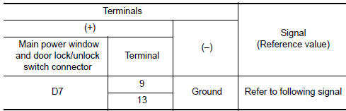
1.CHECK ENCODER OPERATION
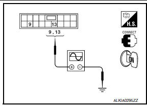
- Turn ignition switch ON.
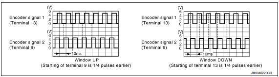
- Check signal between main power window and door lock/unlock switch connector D7 terminals 9, 13 and ground with oscilloscope.
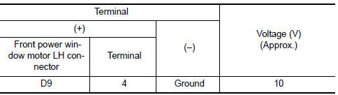
2. CHECK ENCODER POWER SUPPLY
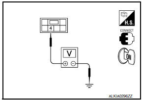
Check voltage between front power window motor LH connector D9 terminal 4 and ground.
3. CHECK HARNESS CONTINUITY 1
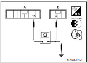
- Turn ignition switch OFF.
- Disconnect main power window and door lock/unlock switch connector D7 and front power window motor LH connector.
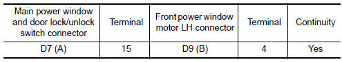
- Check continuity between main power window and door lock/ unlock switch connector D7 (A) terminal 15 and front power window motor LH connector D9 (B) terminal 4.
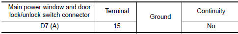
- Check continuity between main power window and door lock/unlock switch connector D7 (A) terminal 15 and ground.
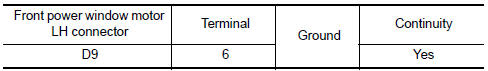
4. CHECK ENCODER GROUND CIRCUIT
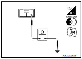
- Turn ignition switch OFF.
- Disconnect front power window motor LH connector.
- Check continuity between front power window motor LH connector D9 terminal 6 and ground.
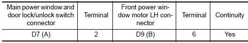
5. CHECK HARNESS CONTINUITY 2
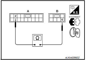
- Disconnect main power window and door lock/unlock switch connector D7.
- Check continuity between main power window and door lock/ unlock switch connector D7 (A) terminal 2 and front power window motor LH connector D9 (B) terminal 6.
6. CHECK HARNESS CONTINUITY 3
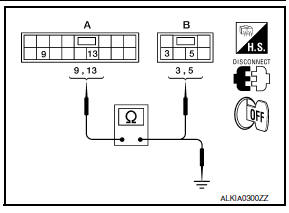
- Disconnect main power window and door lock/unlock switch connector D7.
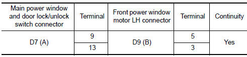
- Check continuity between main power window and door lock/ unlock switch connector D7 (A) terminals 9, 13 and front power window motor LH connector D9 (B) terminals 3, 5.
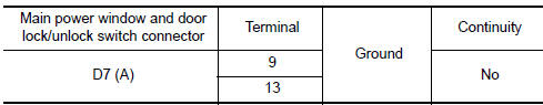
- Check continuity between main power window and door lock/unlock switch connector D7 (A) terminals 9, 13 and ground.
DRIVER SIDE : Special Repair Requirement
1. PERFORM INITIALIZATION PROCEDURE
Perform initialization procedure.
2. CHECK ANTI-PINCH OPERATION
Check anti-pinch operation.
PASSENGER SIDE
PASSENGER SIDE : Description
Detects condition of the front power window motor RH operation and transmits to power window and door lock/unlock switch RH as pulse signal.
PASSENGER SIDE : Component Function Check
1.CHECK ENCODER OPERATION
Check that front door glass RH performs AUTO open/close operation normally when operating power window and door lock/unlock switch RH.
PASSENGER SIDE : Diagnosis Procedure
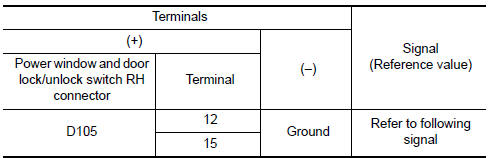
1. CHECK ENCODER SIGNAL
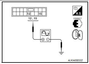
- Turn ignition switch ON.
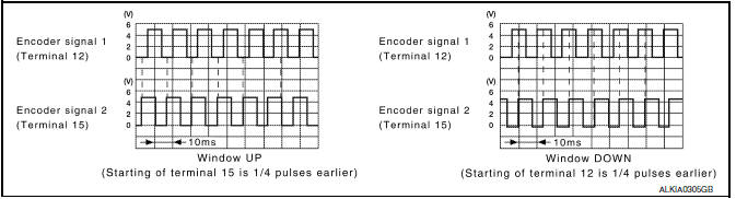
- Check signal between power window and door lock/unlock switch RH connector D105 terminal 12, 15 and ground with oscilloscope.
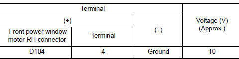
2. CHECK ENCODER POWER SUPPLY
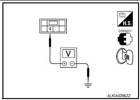
Check voltage between front power window motor RH connector D104 terminal 4 and ground.
3. CHECK HARNESS CONTINUITY 1
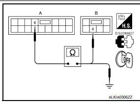
- Turn ignition switch OFF.
- Disconnect power window and door lock/unlock switch RH and front power window motor RH connectors.
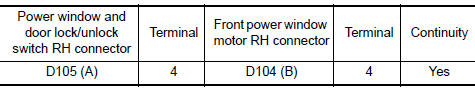
- Check continuity between power window and door lock/unlock switch RH connector D105 (A) terminal 4 and front power window motor RH connector D104 (B) terminal 4.
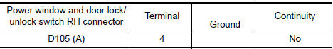
- Check continuity between power window and door lock/unlock switch RH connector D105 (A) terminal 4 and ground.
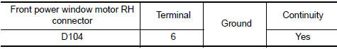
4. CHECK ENCODER GROUND CIRCUIT
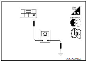
- Turn ignition switch OFF.
- Disconnect front power window motor RH connector.
- Check continuity between front power window motor RH connector D104 terminal 6 and ground.
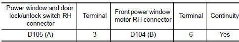
5. CHECK HARNESS CONTINUITY 2

- Disconnect power window and door lock/unlock switch RH connector.
- Check continuity between power window and door lock/unlock switch RH connector D105 (A) terminal 3 and front power window motor RH connector D104 (B) terminal 6.
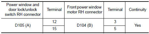
6. CHECK HARNESS CONTINUITY 3
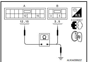
- Disconnect power window and door lock/unlock switch RH connector.
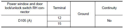
- Check continuity between power window and door lock/unlock switch RH connector D105 (A) terminals 12, 15 and front power window motor RH connector D104 (B) terminals 3, 5.
- Check continuity between power window and door lock/unlock switch RH connector D105 (A) terminals 12, 15 and ground.
PASSENGER SIDE : Special Repair Requirement
1. PERFORM INITIALIZATION PROCEDURE
Perform initialization procedure.
2. CHECK ANTI-PINCH OPERATION
Check anti-pinch operation.
 Power window motor
DRIVER SIDE
DRIVER SIDE : Description
Door glass moves UP/DOWN by receiving the signal from main power window and
door lock/unlock switch.
DRIVER SIDE : Component Function Check
1. CHECK FRONT P ...
 Door switch
Description
Detects front door open/close condition.
Component Function Check
1.CHECK FUNCTION
With CONSULT
Check front door switches DOOR SW-DR and DOOR SW-AS in Data Monitor mode with
CONSULT ...
Other materials:
Steering angle sensor
Exploded View
Steering angle sensor
Screw
Front
Removal and Installation
REMOVAL
Remove the spiral cable. Refer to SR-15, "Removal and
Installation".
Remove the screws (A) and release the clips (B) to remove the
steering angle sensor (1) from the spir ...
HVAC branch line circuit
Diagnosis Procedure
1.CHECK CONNECTOR
Turn the ignition switch OFF.
Disconnect the battery cable from the negative terminal.
Check the terminals and connectors of the A/C auto amp. for
damage, bend and loose connection (unit
side and connector side).
2.CHECK HARNESS FOR OPEN CIRCUI ...
Wind deflector
Removal and Installation
REMOVAL
Open the glass lid.
Remove the side screw (A) to release the wind deflector side
arms (1). : Front
Disconnect and release the inner blind (1) slide clip from wind
deflector.
: Front
Remove the front screws (A), then remove wind deflector ...
Nissan Maxima Owners Manual
- Illustrated table of contents
- Safety-Seats, seat belts and supplemental restraint system
- Instruments and controls
- Pre-driving checks and adjustments
- Monitor, climate, audio, phone and voice recognition systems
- Starting and driving
- In case of emergency
- Appearance and care
- Do-it-yourself
- Maintenance and schedules
- Technical and consumer information
Nissan Maxima Service and Repair Manual

0.0065