Nissan Maxima Service and Repair Manual: Door switch
Description
Detects front door open/close condition.
Component Function Check
1.CHECK FUNCTION
With CONSULT
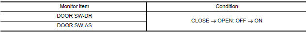
Check front door switches DOOR SW-DR and DOOR SW-AS in Data Monitor mode with CONSULT.
Diagnosis Procedure
1.CHECK FRONT DOOR SWITCH INPUT SIGNAL
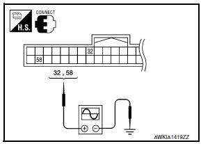
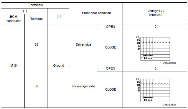
- Turn ignition switch OFF.
- Check signal between BCM connector and ground with oscilloscope.
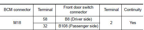
2.CHECK FRONT DOOR SWITCH CIRCUIT
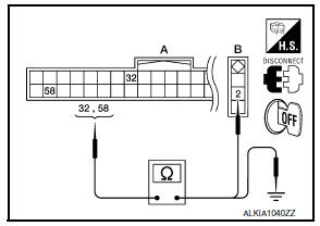
- Disconnect BCM connector.
- Check continuity between BCM connector and front door switch connector.
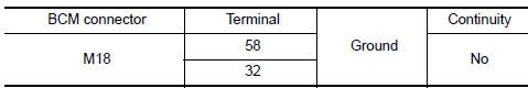
- Check continuity between BCM connector and ground.
3.CHECK FRONT DOOR SWITCH
4.CHECK INTERMITTENT INCIDENT
Component Inspection
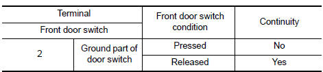
1.CHECK FRONT DOOR SWITCH
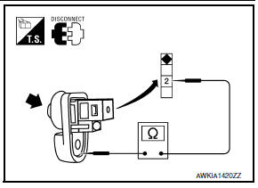
- Turn ignition switch OFF.
- Disconnect front door switch connector.
- Check front door switch.
 Encoder
DRIVER SIDE
DRIVER SIDE : Description
Detects condition of the front power window motor LH operation and transmits
to main power window and door
lock/unlock switch as pulse signal.
DRIVER SIDE ...
 Door key cylinder switch
Description
The main power window and door lock/unlock switch detects condition of the
door key cylinder switch and
transmits to BCM as the LOCK or UNLOCK signal.
Component Function Check
1.CHE ...
Other materials:
Precaution
PRECAUTIONS
Precaution for Supplemental Restraint System (SRS) "AIR BAG" and "SEAT BELT
PRE-TENSIONER"
The Supplemental Restraint System such as "AIR BAG" and "SEAT BELT
PRE-TENSIONER", used along
with a front seat belt, helps to reduce the risk or severity of injury to the
driver and fron ...
Unit disassembly and assembly
DOOR MIRROR
Exploded View
Door mirror glass
Actuator assembly
Door mirror assembly
Disassembly
Turn the door mirror glass surface upward.
Pull from the bottom to disengage lower clips
Lift to disengage the upper mirror hooks (A).
Disconnect the harness connect ...
CVT fluid
Inspection
CHECKING CVT FLUID
The fluid level should be checked with the fluid warmed
up to 50 to 80C (122 to 176F). The fluid level
check procedure is as follows:
Check for fluid leakage.
With the engine warmed up, drive the vehicle in
an urban area.
When amb ...
Nissan Maxima Owners Manual
- Illustrated table of contents
- Safety-Seats, seat belts and supplemental restraint system
- Instruments and controls
- Pre-driving checks and adjustments
- Monitor, climate, audio, phone and voice recognition systems
- Starting and driving
- In case of emergency
- Appearance and care
- Do-it-yourself
- Maintenance and schedules
- Technical and consumer information
Nissan Maxima Service and Repair Manual

0.0066