Nissan Maxima Service and Repair Manual: B2560 starter control relay
Description
Starter control relay, integrated in IPDM E/R, permits the starter relay operation when in N or P position. It is installed in parallel with the starter relay.
DTC Logic
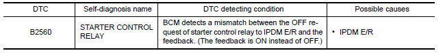
DTC DETECTION LOGIC
NOTE:
-
If DTC B2560 is displayed with DTC U1000, first perform the trouble diagnosis for DTC U1000. Refer to SEC-29, "DTC Logic".
-
If DTC B2560 is displayed with DTC U1010, first perform the trouble diagnosis for DTC U1010. Refer to SEC-30, "DTC Logic".
DTC CONFIRMATION PROCEDURE
1.PERFORM DTC CONFIRMATION PROCEDURE
-
Turn ignition switch ON under the following conditions and wait for at least 2 seconds:
-
CVT selector lever is in the P position.
-
Depress the brake pedal.
-
-
Check "Self Diagnostic Result" with CONSULT.
Diagnosis Procedure
1.CHECK DTC WITH IPDM E/R
Check "Self Diagnostic Result" with CONSULT. Refer to PCS-27, "DTC Index".
2.CHECK INTERMITTENT INCIDENT
Refer to GI-41, "Intermittent Incident".
Inspection End.
 B2557 vehicle speed
Description
BCM receives the 2 vehicle speed signals via CAN
communication. One signal is transmitted by the "combination
meter". Another signal is transmitted by "ABS actuator and electric unit ...
 B2601 shift position
Description
BCM confirms the shift position with the following 2
signals.
CVT selector lever
P position signal from IPDM E/R (CAN)
DTC Logic
DTC DETECTION LOGIC
N ...
Other materials:
Insufficient heating
Component Function Check
Symptom
Insufficient heating
No warm air comes out. (Airflow volume is normal.)
INSPECTION FLOW
1. CONFIRM SYMPTOM BY PERFORMING OPERATION CHECK - TEMPERATURE INCREASE
Press the AUTO switch.
Turn temperature control switch (driver side) clockwise until 32C
...
C1105, C1106, C1107, C1108 wheel sensor
DTC Logic
DTC DETECTION LOGIC
DTC CONFIRMATION PROCEDURE
1.CHECK SELF DIAGNOSTIC RESULT
With CONSULT.
Start engine and drive vehicle at approximately 21 km/h (13 MPH)
or more for approximately 5 minutes.
Perform self diagnostic result
Diagnosis Procedure
CAUTION:
Do not check ...
Variable induction air system
Description
Power Valves 1 and 2
The power valves 1 and 2 are installed in intake manifold collector and used to
control the suction passage of
the variable induction air control system. They are set in the fully closed or
fully opened position by the power
valve actuators 1 and 2 operate ...
Nissan Maxima Owners Manual
- Illustrated table of contents
- Safety-Seats, seat belts and supplemental restraint system
- Instruments and controls
- Pre-driving checks and adjustments
- Monitor, climate, audio, phone and voice recognition systems
- Starting and driving
- In case of emergency
- Appearance and care
- Do-it-yourself
- Maintenance and schedules
- Technical and consumer information
Nissan Maxima Service and Repair Manual

0.0074