Nissan Maxima Service and Repair Manual: P0868 transmission fluid pressure
Description
The secondary pressure solenoid valve regulates the secondary pressure to suit the driving condition in response to a signal sent from the TCM.
DTC Logic
DTC DETECTION LOGIC

DTC CONFIRMATION PROCEDURE
CAUTION: Always drive vehicle at a safe speed.
NOTE: Immediately after performing any "DTC CONFIRMATION PROCEDURE", always turn ignition switch OFF.
Then wait at least 10 seconds before performing the next test.
1.CHECK DTC DETECTION
 With CONSULT
-
Turn ignition switch ON.
-
Select "Data Monitor" in "TRANSMISSION".
-
Check that output voltage of CVT fluid temperature sensor is within the range below.
ATF TEMP SEN : 1.0 - 2.0 V
If it is out of range, drive the vehicle to decrease the voltage (warm up the fluid) or stop engine to increase the voltage (cool down the fluid)
4. Start engine and maintain the following conditions for at least 10 consecutive seconds.
VEHICLE SPEED (accelerate slowly) : 0 → 50 km/h (31 MPH)
ACC PEDAL OPEN : 0.5/8 - 1.0/8
RANGE : "D" position
Diagnosis Procedure
1.CHECK LINE PRESSURE
Perform line pressure test. Refer to TM-162, "Inspection and Judgment".
2.CHECK SECONDARY PRESSURE SOLENOID VALVE
-
Turn ignition switch OFF.
-
Disconnect CVT unit connector.
-
Check secondary pressure solenoid valve. Refer to TM-94, "Component Inspection (Secondary Pressure Solenoid Valve)".
3.CHECK LINE PRESSURE SOLENOID VALVE
Check line pressure solenoid valve. Refer to TM-94, "Component Inspection (Line Pressure Solenoid Valve)".
4.CHECK SECONDARY PRESSURE SENSOR SYSTEM
Check secondary pressure sensor system. Refer to TM-85, "DTC Logic".
5.DETECT MALFUNCTIONING ITEMS
Check TCM connector pin terminals for damage or loose connection with harness connector.
Component Inspection (Line Pressure Solenoid Valve)
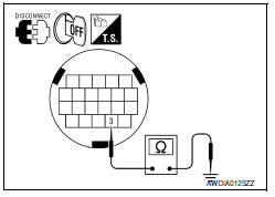
1.CHECK LINE PRESSURE SOLENOID VALVE
Check resistance between CVT unit connector terminal and ground.


Component Inspection (Secondary Pressure Solenoid Valve)
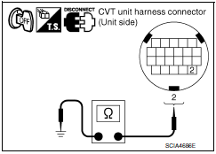
1.CHECK SECONDARY PRESSURE SOLENOID VALVE
Check resistance between CVT unit connector terminal and ground.


 P0845 transmission fluid pressure SEN/SW B
Description
The primary pressure sensor detects primary pressure of CVT and sends a
signal to the TCM.
DTC Logic
DTC DETECTION LOGIC
DTC CONFIRMATION PROCEDURE
NOTE:
Immediately after perfo ...
 P1701 TCM
Description
When the power supply to the TCM is cut off, for example
because the battery is removed, and the self-diagnosis
memory function stops, a malfunction is detected.
NOTE:
Since "P1701 ...
Other materials:
Periodic maintenance
FOR USA AND CANADA
FOR USA AND CANADA : Introduction of Periodic Maintenance
The following tables show the normal maintenance schedule. Depending upon
weather and atmospheric conditions,
varying road surfaces, individual driving habits and vehicle usage, additional
or more frequent maintenan ...
Door lock and unlock switch
DRIVER SIDE
DRIVER SIDE : Description
Transmits door lock/unlock operation to BCM.
DRIVER SIDE : Component Function Check
1. CHECK FUNCTION
With CONSULT
Check CDL LOCK SW, CDL UNLOCK SW in Data Monitor mode with CONSULT
DRIVER SIDE : Diagnosis Procedure
1. CHECK POWER WINDOW SWITCH OUTP ...
B2098 ignition relay on stuck
DTC Logic
DTC DETECTION LOGIC
1.PERFORM DTC CONFIRMATION PROCEDURE
Turn the power supply position to start under the following
conditions and wait for at least 1 second.
CVT selector lever is in the P (Park) or N (Neutral) position.
Depress the brake pedal
Check "Self-diag ...
Nissan Maxima Owners Manual
- Illustrated table of contents
- Safety-Seats, seat belts and supplemental restraint system
- Instruments and controls
- Pre-driving checks and adjustments
- Monitor, climate, audio, phone and voice recognition systems
- Starting and driving
- In case of emergency
- Appearance and care
- Do-it-yourself
- Maintenance and schedules
- Technical and consumer information
Nissan Maxima Service and Repair Manual
0.0062
