Nissan Maxima Service and Repair Manual: P1701 TCM
Description
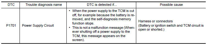
When the power supply to the TCM is cut off, for example because the battery is removed, and the self-diagnosis memory function stops, a malfunction is detected.
NOTE: Since "P1701" is indicated when replacing TCM, perform diagnosis after erasing "Self Diagnostic Results".
DTC Logic
DTC DETECTION LOGIC
DTC CONFIRMATION PROCEDURE
NOTE: Immediately after performing any "DTC CONFIRMATION PROCEDURE", always turn ignition switch OFF.
Then wait at least 10 seconds before performing the next test.
1.CHECK DTC DETECTION
 With CONSULT
-
Turn ignition switch ON.
-
Wait for at least 2 consecutive seconds.
-
Perform "Self Diagnostic Results" in "TRANSMISSION".
Diagnosis Procedure
Regarding Wiring Diagram information, refer to TM-126, "Wiring Diagram".
1.CHECK TCM POWER SOURCE
-
Turn ignition switch OFF.
-
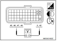
Disconnect TCM connector.
-
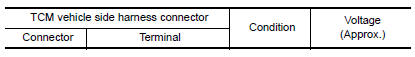
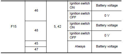
Check voltage between TCM vehicle side harness connector terminals.
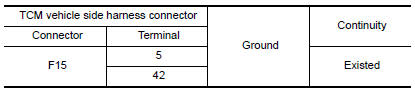
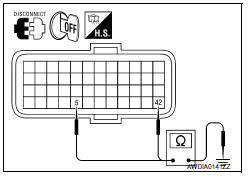
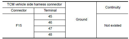
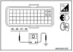
2.CHECK TCM GROUND CIRCUIT
-
Turn ignition switch OFF.
-
Check continuity between TCM vehicle side harness connector terminals and ground.
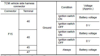
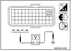
3.CHECK TCM POWER CIRCUIT
Check voltage between TCM vehicle side harness connector terminals and ground.
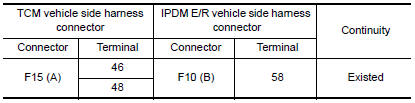
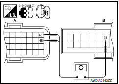
4.CHECK HARNESS BETWEEN TCM AND IPDM E/R AND BETWEEN TCM AND BATTERY (PART 1)
-
Turn ignition switch OFF.
-
Disconnect IPDM E/R connector.
-
Check continuity between TCM vehicle side harness connector terminals and IPDM E/R vehicle side harness connector terminal.
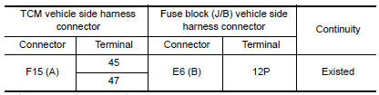
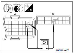
4. Disconnect fuse block (J/B) connector.
5. Check continuity between TCM vehicle side harness connector terminals and fuse block (J/B) vehicle side harness connector terminal.
5.CHECK HARNESS BETWEEN TCM AND IPDM E/R AND BETWEEN TCM AND BATTERY (PART 2)
Check continuity between TCM vehicle side harness connector terminals and ground.
6.DETECT MALFUNCTIONING ITEMS
Check TCM connector pin terminals for damage or loose connection with harness connector.
 P0868 transmission fluid pressure
Description
The secondary pressure solenoid valve regulates the
secondary pressure to suit the driving condition in
response to a signal sent from the TCM.
DTC Logic
DTC DETECTION LOGIC
DTC ...
 P1705 TP sensor
Description
The electric throttle control actuator consists of
throttle control motor, accelerator pedal position sensor, throttle
position sensor, etc. The actuator sends a signal to the ECM, an ...
Other materials:
Lifting switch (rear)
Description
Lifting switch (rear) is equipped to the power seat switch LH on the seat
frame. The operation signal is inputted to the driver seat control unit when
the lifting switch (rear) is operated.
Component Function Check
1. CHECK FUNCTION
Select "LIFT RR SW-UP", "LIFT RR SW-DN" in " ...
Rear power window switch
Removal and Installation
REMOVAL
Remove the rear door armrest finisher. Refer to INT-21,
"Removal and Installation".
Release the pawls on each side to separate the switch finisher
(1) from the rear power window switch (2) using a suitable tool
(A).
: Pawl
INSTALLA ...
Remove
Use the following procedure to remove the head
restraint/headrest:
1. Pull the head restraint/headrest up to the
highest position.
2. Push and hold the lock knob.
3. Remove the head restraint/headrest from
the seat.
4. Store the head restraint/headrest properly in
a secure place so i ...
Nissan Maxima Owners Manual
- Illustrated table of contents
- Safety-Seats, seat belts and supplemental restraint system
- Instruments and controls
- Pre-driving checks and adjustments
- Monitor, climate, audio, phone and voice recognition systems
- Starting and driving
- In case of emergency
- Appearance and care
- Do-it-yourself
- Maintenance and schedules
- Technical and consumer information
Nissan Maxima Service and Repair Manual

0.0075