Nissan Maxima Service and Repair Manual: Antenna AMP
Removal and Installation
REMOVAL
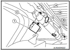
- Remove the rear pillar finisher RH. Refer to INT-23, "Exploded View".
- Detach the antenna amp. harness clip (A).
- Disconnect the harness connectors (B) from the antenna amp. (1).
- Remove the antenna amp. screw (C) and the antenna amp. (1).
INSTALLATION
Installation is in the reverse order of removal.
 Audio antenna
Location of Antenna
AV control unit
AV control unit antenna feeder
In-line connectors M103, M501
Antenna amp.
Window antenna
Satellite radio antenna feeder
Satellite radio anten ...
 Microphone
Removal and Installation
REMOVAL
Remove the front room/map lamp assembly. Refer to INL-84, "Removal and
Installation".
Detach the microphone connector (A).
Remove the ...
Other materials:
P1551, P1552 battery current sensor
Description
The power generation voltage variable control enables fuel consumption to be
decreased by reducing the
engine load which is caused by the power generation of the generator. The
battery current sensor is installed
to the battery cable at the negative terminal. The sensor measures ...
Automatic air conditioner system
System Diagram
CONTROL SYSTEM
The control system consists of input sensors, switches, the A/C auto amp.
(microcomputer) and outputs. The
relationship of these components is as shown in the figure below:
System Description
CONTROL OPERATION
Display
The operation status of the HVAC system ...
RGB (B: blue) signal circuit
Description
Transmit the image displayed with AV control unit with RGB signal to the
display unit.
Diagnosis Procedure
1.CHECK CONTINUITY RGB (B: BLUE) SIGNAL CIRCUIT
Turn ignition switch OFF.
Disconnect display unit connector M141 and AV control unit
connector
M154.
Check con ...
Nissan Maxima Owners Manual
- Illustrated table of contents
- Safety-Seats, seat belts and supplemental restraint system
- Instruments and controls
- Pre-driving checks and adjustments
- Monitor, climate, audio, phone and voice recognition systems
- Starting and driving
- In case of emergency
- Appearance and care
- Do-it-yourself
- Maintenance and schedules
- Technical and consumer information
Nissan Maxima Service and Repair Manual

0.0074