Nissan Maxima Service and Repair Manual: Audio antenna
Location of Antenna
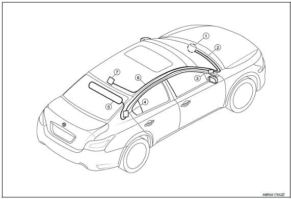
- AV control unit
- AV control unit antenna feeder
- In-line connectors M103, M501
- Antenna amp.
- Window antenna
- Satellite radio antenna feeder
- Satellite radio antenna
Window Antenna Repair
ELEMENT CHECK
- Attach probe circuit tester (ohm setting) to antenna terminal on each side.
- When measuring continuity, wrap tin foil around the top of probe. Then, press the foil against the wire with your finger.
- If an element is broken, no continuity will exist.
- To locate a break, move probe along element. Tester indication will change abruptly when probe passes the broken point.
REPAIR EQUIPMENT
- Conductive silver composition (DuPont No. 4817 or equivalent)
- Ruler 30 cm (11.8 in) long
- Drawing pen
- Heat gun
- Alcohol
- Cloth
REPAIRING PROCEDURE
- Wipe broken heat wire and its surrounding area clean with a cloth dampened in alcohol.
- Apply a small amount of conductive silver composition to tip of drawing pen. NOTE: Shake silver composition container before use.
- Place ruler on glass along broken line. Deposit conductive silver composition on break with drawing pen. Slightly overlap existing heat wire on both sides [preferably 5 mm (0.20 in)] of the break.
- After repair has been completed, check repaired wire for continuity.
This check should be conducted 10 minutes after silver composition is deposited.
Do not touch repaired area while test is being conducted.
- Apply a constant stream of hot air directly to the repaired area
for approximately 20 minutes with a heat gun. A minimum distance
of 3 cm (1.2 in) should be kept between repaired area and
hot air outlet.
If a heat gun is not available, let the repaired area dry for 24 hours.
 Steering switch
Removal and Installation
REMOVAL
Remove the driver airbag module. Refer to SR-12, "Removal and
Installation".
Remove the steering wheel audio control switch screws (A).
Relea ...
 Antenna AMP
Removal and Installation
REMOVAL
Remove the rear pillar finisher RH. Refer to INT-23, "Exploded
View".
Detach the antenna amp. harness clip (A).
Disconnect the harness connec ...
Other materials:
Rear disc brake
Exploded View of Brake Pads
Inner shim cover
Inner shim
Inner pad
Pad retainer
Outer pad
Outer shim
Outer shim cover
Molykote AS-880N grease
Molykote 7439 grease
Removal and Installation of Brake Pads
WARNING:
Clean dust on caliper and brake pad with a vacuum dust ...
P0442 evap control system
DTC Logic
DTC DETECTION LOGIC
This diagnosis detects leakage in the EVAP purge line using engine intake
manifold vacuum.
If pressure does not increase, the ECM will check for leakage in the line
between the fuel tank and EVAP canister
purge volume control solenoid valve, under the followi ...
Trunk opener request switch
Removal and Installation
REMOVAL
Remove the license lamp finisher (1). Refer to EXL-166, "Removal
and Installation".
Remove the inner bracket screws (A) and inner bracket (2) from
license lamp finisher (1).
Remove the trunk lid request switch screw (B) and trunk lid
req ...
Nissan Maxima Owners Manual
- Illustrated table of contents
- Safety-Seats, seat belts and supplemental restraint system
- Instruments and controls
- Pre-driving checks and adjustments
- Monitor, climate, audio, phone and voice recognition systems
- Starting and driving
- In case of emergency
- Appearance and care
- Do-it-yourself
- Maintenance and schedules
- Technical and consumer information
Nissan Maxima Service and Repair Manual

0.0058