Nissan Maxima Service and Repair Manual: Rear disc brake
Exploded View of Brake Pads
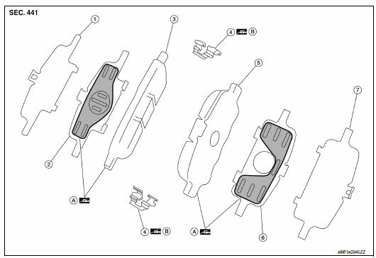
- Inner shim cover
- Inner shim
- Inner pad
- Pad retainer
- Outer pad
- Outer shim
- Outer shim cover
- Molykote AS-880N grease
- Molykote 7439 grease
Removal and Installation of Brake Pads
WARNING: Clean dust on caliper and brake pad with a vacuum dust collector to minimize the hazard of air borne particles or other materials.
CAUTION:
- While removing and installing cylinder body, do not depress brake pedal because piston will pop out.
- It is not necessary to remove bolts on torque member and brake hose except for disassembly or replacement of caliper assembly. For pad removal and installation, hang cylinder body with a wire so as not to stretch brake hose.
- Do not damage piston boot.
- If any shim is subject to serious corrosion, replace it with a new one.
- Always replace shim and shim covers as a set when replacing brake pads.
- Keep rotor and pads free from grease and brake fluid.
- Burnish the brake pads and disc rotor mutually contacting surfaces after refinishing or replacing rotors, after replacing pads, or if a soft pedal occurs at very low mileage. Refer to BR-35, "Brake Burnishing Procedure".
REMOVAL
- Partially drain brake fluid from the master cylinder.
- Remove the rear wheel and tire using power tool. Refer to WT-60, "Adjustment".
- Remove the upper sliding pin bolt and loosen the lower sliding pin bolt to swing the cylinder body down.
- Remove the pads, pad retainers, shims, and shim covers from the torque member.
CAUTION: Do not deform the pad retainers when removing them from the torque member.
INSTALLATION
- Apply Molykote AS-880N grease or equivalent to between shim covers and shims. Install inner shim, inner shim cover to inner pad. Install outer shim and outer shim cover to outer pad.
- Apply Molykote 7439 grease (A) or equivalent to between pad retainer and pad. Install pad retainers and pads to torque member.
- Press in piston using suitable tool, until the pads can be
installed, and then install the cylinder body in the torque member.
CAUTION: When replacing pads with new set, check the brake fluid level in the reservoir tank because brake fluid returns to the master cylinder reservoir tank when pressing in the piston. - Install upper sliding pin bolt and tighten the upper and lower sliding pin bolts to the specified torque.
- Check the rear disc brakes for drag.
- Install the rear wheel and tire. Refer to WT-60, "Adjustment".
- Check brake fluid level and refill as necessary. Refer to BR-16, "Inspection".
Brake Burnishing Procedure
Burnish contact surfaces between disc rotors and pads according to following procedure after refinishing or replacing rotors, after replacing pads, or if a soft pedal occurs at very low mileage.
CAUTION:
- Be careful of vehicle speed because the brake does not operate easily until pad and disc rotor are securely fitted.
- Only perform this procedure under safe road and traffic conditions. Use extreme caution.
- Drive vehicle on straight, flat road.
- Depress brake pedal with the power to stop vehicle within 3 to 5 seconds until the vehicle stops.
- Drive without depressing brake for a few minutes to cool the brake.
- Repeat steps 1 to 3 until pad and disc rotor are securely fitted.
Exploded View of Brake Caliper
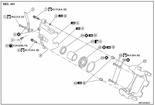
- Union bolt
- Brake hose
- Copper sealing washer
- Cap
- Bleed valve
- Lower sliding pin bolt
- Upper sliding pin bolt
- Bushing
- Cylinder body
- Piston seal
- Piston
- Piston boot
- Retaining ring
- Sliding pin boot
- Torque member bolt
- Washer
- Torque member
- Molykote AS-880N grease
- Brake grease
- Brake fluid
Removal and Installation of Brake Caliper and Rotor
WARNING: Clean dust on caliper and brake pad with a vacuum dust collector to minimize the hazard of air borne particles or other materials.
CAUTION:
- While removing and installing the cylinder body, do not depress the brake pedal because the piston will pop out.
- Do not damage the piston boot.
- Keep rotor free from grease and brake fluid.
- Refill the brake reservoir with new brake fluid.
- Do not reuse drained brake fluid.
NOTE: When removing components such as hoses, tubes/lines, etc., cap or plug openings to prevent fluid from spilling.
REMOVAL
- Remove the rear wheel and tire using power tool. Refer to WT-60, "Adjustment".
- Hold the disc rotor in place by installing a wheel nut.
- Remove the reservoir cap.
- Remove the union bolt and copper sealing washers, then disconnect
the brake hose from the cylinder body. Discard the copper
sealing washers.
CAUTION: Do not reuse copper sealing washers. - Remove the torque member bolts, and remove the brake caliper
assembly.
CAUTION: Do not drop brake the pads.
- Remove upper and lower sliding pins.
NOTE: Note the sliding pin orientation during removal. The upper sliding pin contains a bushing. - Remove caliper.
- Remove the disc rotor. If reusing the disc rotor, before removing
the disc rotor apply matching mark as shown.
CAUTION: Put matching marks on wheel hub assembly and disc rotor, if reusing the disc rotor.
INSTALLATION
- Install the disc rotor. If reusing the disc rotor, align the matching
mark to position the disc rotor on the wheel hub assembly.
CAUTION: Align the matching mark on wheel hub assembly and disc rotor, if reusing the disc rotor.
- Install the brake caliper assembly, and tighten the torque member bolts
to the specified torque.
CAUTION: Before installing caliper assembly, wipe off oil and moisture on all mounting surfaces of rear axle and caliper assembly and threads, bolts and washers. - Install the brake hose with two new copper sealing washers (1),
using the L-shaped pin for alignment as shown, then tighten the
union bolt (A) to the specified torque.
CAUTION: Do not reuse copper sealing washers. - Refill the brake hydraulic system with new brake fluid and bleed brake system. Refer to BR-16, "Bleeding Brake System".
- Check the rear disc brakes for drag.
- Install the reservoir cap.
- Install the rear wheel and tire. Refer to WT-60, "Adjustment".
 Front disc brake
Exploded View of Brake Pads
Inner shim cover
Inner shim
Inner pad
Outer pad
Outer shim
Outer shim cover
Anti-rattle clips
Pad retainers
Molykote AS-880N grease
Mo ...

Other materials:
Vertical synchronizing (VP) signal circuit
Description
In composite image (AUX image, camera image), transmit the vertical
synchronizing (VP) signal and horizontal
synchronizing (HP) signal from display unit to AV control unit so as to
synchronize the RGB images displayed
with AV control unit, such as the image quality adjusting men ...
Checking engine oil level
1. Park the vehicle on a level surface and apply
the parking brake.
2. Start the engine and let it idle until it reaches
operating temperature.
3. Turn off the engine. Wait more than
10 minutes for the oil to drain back into
the oil pan.
4. Remove the dipstick and wipe it clean. Rei ...
Removal and installation
EXHAUST SYSTEM
Exploded View
Front exhaust tube
Ring gasket
Front exhaust tube stay
Front exhaust tube bracket
Gasket
Center exhaust tube rubber hanger
Center exhaust tube
Center exhaust tube hanger
Rear muffler bracket (RH)
Rear muffler (RH)
Rear muffler bracket (LH) ...
Nissan Maxima Owners Manual
- Illustrated table of contents
- Safety-Seats, seat belts and supplemental restraint system
- Instruments and controls
- Pre-driving checks and adjustments
- Monitor, climate, audio, phone and voice recognition systems
- Starting and driving
- In case of emergency
- Appearance and care
- Do-it-yourself
- Maintenance and schedules
- Technical and consumer information
Nissan Maxima Service and Repair Manual

0.0071