Nissan Maxima Service and Repair Manual: Power supply and ground circuit
Diagnosis Procedure
1.CHECK GROUND CONNECTION-I
- Turn ignition switch OFF.
- Check ground connection E9. Refer to Ground Inspection
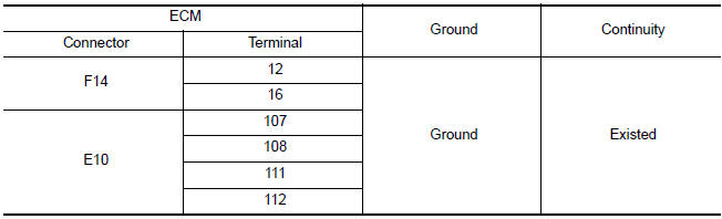
2.CHECK ECM GROUND CIRCUIT FOR OPEN AND SHORT-I
- Disconnect ECM harness connector.
- Check the continuity between ECM harness connector and ground.
- Also check harness for short to power.
3.DETECT MALFUNCTIONING PART
Check the following.
- Harness connectors E11, F2
- Harness for open or short between ECM and ground
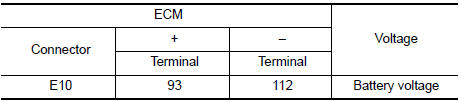
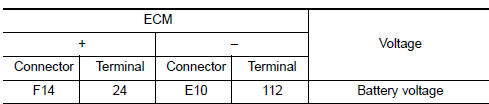
4.CHECK ECM POWER SUPPLY CIRCUIT-I
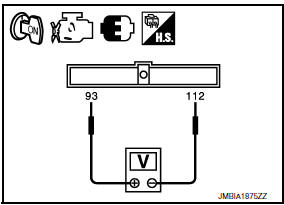
- Reconnect ECM harness connector.
- Turn ignition switch OFF and then ON.
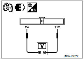
- Check the voltage between ECM harness connectors.
5.DETECT MALFUNCTIONING PART
Check the following.
- IPDM E/R connector E18
- 10 A fuse (No. 35)
- Harness for open or short between ECM and fuse
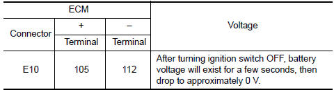
6.CHECK ECM POWER SUPPLY CIRCUIT-II
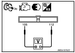
- Turn ignition switch OFF and wait at least 10 seconds.
- Check the voltage between ECM harness connectors.
7.CHECK ECM POWER SUPPLY CIRCUIT-III
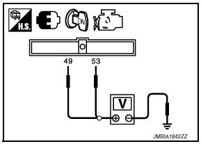
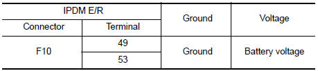
- Turn ignition switch ON.
- Check the voltage between IPDM E/R harness connector and ground.
8.CHECK INTERMITTENT INCIDENT
9.CHECK ECM POWER SUPPLY CIRCUIT-IV
- Turn ignition switch OFF and wait at least 10 seconds.
- Check the voltage between ECM harness connectors.
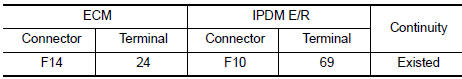
10.CHECK ECM POWER SUPPLY CIRCUIT-V
- Disconnect ECM harness connector.
- Disconnect IPDM E/R harness connector.
- Check the continuity between ECM harness connector and IPDM E/R harness connector.
- Also check harness for short to ground and short to power.
11.CHECK 15 A FUSE
- Disconnect 15 A fuse (No. 42) from IPDM E/R.
- Check 15 A fuse.
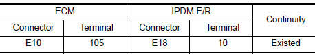
12.CHECK ECM POWER SUPPLY CIRCUIT-VI
- Disconnect ECM harness connector.
- Disconnect IPDM E/R harness connector.
- Check the continuity between ECM harness connector and IPDM E/R harness connector.
- Also check harness for short to ground and short to power.
13.DETECT MALFUNCTIONING PART
Check the following.
- Junction block connectors E44, E45
- Harness for open or short between ECM and IPDM E/R
14.CHECK INTERMITTENT INCIDENT
 Trouble diagnosis - specification value
Description
The specification (SP) value indicates the tolerance of the value that is
displayed in "SPEC" of "DATA MONITOR"
mode of CONSULT during normal operation of the Engine Control System. W ...
 U0101 can comm circuit
Description
CAN (Controller Area Network) is a serial communication line for real time
application. It is an on-vehicle multiplex
communication line with high data communication speed and excelle ...
Other materials:
Combination switch input circuit
Diagnosis Procedure
1. CHECK INPUT 1 - 5 SYSTEM CIRCUIT FOR OPEN
Turn the ignition switch OFF.
Disconnect the BCM and combination switch.
Check continuity between BCM harness connector and combination
switch harness connector.
2. CHECK INPUT 1 - 5 SYSTEM CIRCUIT FOR SHORT
...
Illumination
Wiring Diagram
...
Parking, license plate and tail lamps are not turned on
Description
The parking, license plate and tail lamps do not turn ON in with any lighting
switch setting.
Diagnosis Procedure
1.COMBINATION SWITCH (LIGHTING AND TURN SIGNAL SWITCH) INSPECTION
Check the combination switch (lighting and turn signal switch).
2.CHECK TAIL LAMP RELAY REQUEST SIGNA ...
Nissan Maxima Owners Manual
- Illustrated table of contents
- Safety-Seats, seat belts and supplemental restraint system
- Instruments and controls
- Pre-driving checks and adjustments
- Monitor, climate, audio, phone and voice recognition systems
- Starting and driving
- In case of emergency
- Appearance and care
- Do-it-yourself
- Maintenance and schedules
- Technical and consumer information
Nissan Maxima Service and Repair Manual

0.0061