Nissan Maxima Service and Repair Manual: Steering switch
Removal and Installation
REMOVAL

- Remove the driver airbag module. Refer to SR-12, "Removal and Installation".
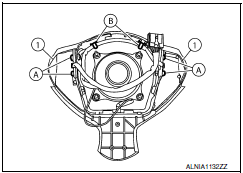
- Remove the steering wheel audio control switch screws (A).
- Release the steering wheel audio control switch harness clips (B).
- Remove the steering wheel audio control switches (1).
INSTALLATION
Installation is in the reverse order of removal.
 Satellite radio antenna
Removal and Installation
REMOVAL
Lower the headlining at the rear. Refer to INT-33, "Exploded
View".
Disconnect the harness connector (A) from satellite radio
antenna.
Remove the sate ...
 Audio antenna
Location of Antenna
AV control unit
AV control unit antenna feeder
In-line connectors M103, M501
Antenna amp.
Window antenna
Satellite radio antenna feeder
Satellite radio antenn ...
Other materials:
Power supply and ground circuit
AV CONTROL UNIT
AV CONTROL UNIT : Diagnosis Procedure
1.CHECK FUSES
Check that the following AV control unit fuses are not blown.
2.POWER SUPPLY CIRCUIT CHECK
Disconnect AV control unit connectors M160 and M163.
Check voltage between the AV control unit connectors M160
and M163 ...
Hazard switch
Component Function Check
1.CHECK HAZARD SWITCH SIGNAL BY CONSULT
CONSULT DATA MONITOR
Turn ignition switch ON.
Select "HAZARD SW" of BCM (FLASHER) DATA MONITOR item.
With operating the hazard switch, check the monitor status.
Diagnosis Procedure
1.CHECK HAZARD SWITCH SIGNAL I ...
Drive mode selector
Drive mode selector switches
Two driving modes can be selected by using the
drive mode selector switches, NORMAL and
SPORT.
NOTE:
When the drive mode select switch selects a
mode, the mode may not switch quickly. This
is not a malfunction.
Select the NORMAL mode for normal driving. ...
Nissan Maxima Owners Manual
- Illustrated table of contents
- Safety-Seats, seat belts and supplemental restraint system
- Instruments and controls
- Pre-driving checks and adjustments
- Monitor, climate, audio, phone and voice recognition systems
- Starting and driving
- In case of emergency
- Appearance and care
- Do-it-yourself
- Maintenance and schedules
- Technical and consumer information
Nissan Maxima Service and Repair Manual
0.0063
