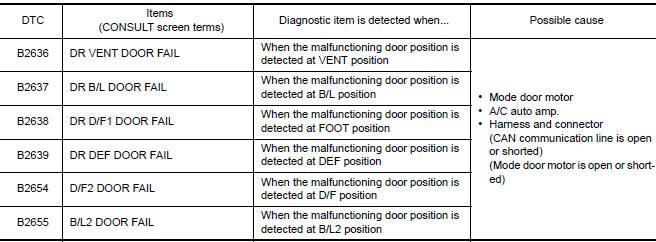
Nissan Maxima Service and Repair Manual: B2636, B2637, B2638, B2639, B2654, B2655 mode door motor
Description
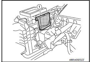
COMPONENT DESCRIPTION
Mode Door Motor
- The mode door motor (1) is attached to the heater & cooling unit assembly.
- It rotates so that air is discharged from the outlet set by the A/C auto amp. Motor rotation is conveyed to a link which activates the mode door.
DTC Logic
DTC DETECTION LOGIC
NOTE: If DTC is displayed along with DTC U1000 or U1010, first diagnose the DTC U1000 or U1010.
DTC CONFIRMATION PROCEDURE
1.CHECK WITH SELF-DIAGNOSIS FUNCTION OF CONSULT
- Using CONSULT, perform "SELF-DIAGNOSIS RESULTS" of HVAC.
- Check if any DTC No. is displayed in the self-diagnosis results.
NOTE: If DTC is displayed along with DTC U1000 or U1010, first diagnose the DTC U1000 or U1010
2.FUNCTION INSPECTION
- Press MODE switch and DEF switch.
- Each position indicator should change shape.
- Confirm that air discharge comes out according to the air distribution table.
NOTE:
Confirm that the A/C compressor clutch is engaged (Sound or visual inspection)
and intake door position is at
FRE ( ) when DEF (
 ) or D/F (
 ) is selected.
Diagnosis Procedure
1.CHECK MODE DOOR MOTOR POWER SUPPLY
- Turn ignition switch ON.
- Check voltage between mode door motor harness connector M127 terminal 1 and ground.
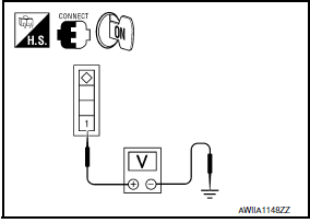
1 - Ground: Battery Voltage
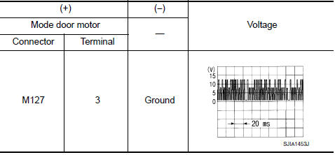
2.CHECK SIGNAL FOR MODE DOOR MOTOR
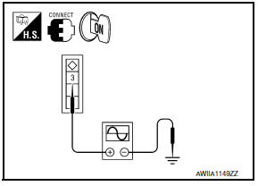
Confirm A/C LAN signal between mode door motor harness connector M127 terminal 3 and ground using an oscilloscope.
3.CHECK MODE DOOR MOTOR GROUND CIRCUIT
- Turn ignition switch OFF.
- Disconnect mode door motor connector.
- Check continuity between mode door motor harness connector M127 terminal 2 and ground.
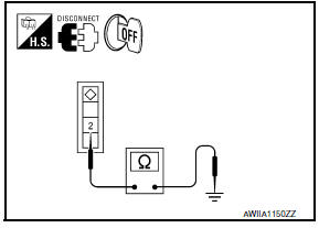
2 - Ground: Continuity should exist.
 B2634, B2635 air mix door motor (passenger side)
Description
COMPONENT DESCRIPTION
Air Mix Door Motor (passenger side)
The air mix door motor (passenger side) (1) is attached to the
heater & cooling unit assembly.
It rotates so that th ...
 B263D, B263E, B263F intake door motor
Description
COMPONENT DESCRIPTION
Intake Door Motor
The intake door motor (1) is attached to the blower unit.
It rotates so that air is drawn from inlets set by the A/C auto
amp.
Motor ...
Other materials:
Antenna AMP
Removal and Installation
REMOVAL
Remove the rear pillar finisher RH. Refer to INT-27, "Exploded
View".
Detach the antenna amp. harness clip (A).
Disconnect the harness connectors (B) from the antenna amp.
(1).
Remove the antenna amp. screw (C) and the antenna amp. (1).
...
Driver air bag module
Exploded View
Driver air bag module
Side lid
Driver air bag module harness connectors
Steering wheel switch assembly connector
Driver air bag module bolt
Removal and Installation
CAUTION:
Before servicing, turn ignition switch OFF, disconnect both
battery terminals and wai ...
IPDM-E branch line circuit
Diagnosis Procedure
1.CHECK CONNECTOR
Turn the ignition switch OFF.
Disconnect the battery cable from the negative terminal.
Check the terminals and connectors of the IPDM E/R for damage,
bend and loose connection (unit side
and connector side).
2.CHECK HARNESS FOR OPEN CIRCUIT
...
Nissan Maxima Owners Manual
- Illustrated table of contents
- Safety-Seats, seat belts and supplemental restraint system
- Instruments and controls
- Pre-driving checks and adjustments
- Monitor, climate, audio, phone and voice recognition systems
- Starting and driving
- In case of emergency
- Appearance and care
- Do-it-yourself
- Maintenance and schedules
- Technical and consumer information
Nissan Maxima Service and Repair Manual

0.0057