
Nissan Maxima Service and Repair Manual: B2634, B2635 air mix door motor (passenger side)
Description
COMPONENT DESCRIPTION
Air Mix Door Motor (passenger side)
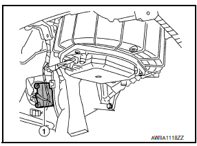
- The air mix door motor (passenger side) (1) is attached to the heater & cooling unit assembly.
- It rotates so that the air mix door is opened or closed to a position set by the A/C auto amp.
- Motor rotation is then conveyed through a shaft and the air mix door position feedback is then sent to the A/C auto amp. by PBR built-in air mix door motor.
DTC Logic
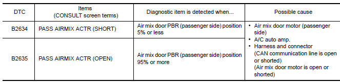
DTC DETECTION LOGIC
NOTE: If DTC is displayed along with DTC U1000 or U1010, first diagnose the DTC U1000 or U1010.
DTC CONFIRMATION PROCEDURE
1.CHECK WITH SELF-DIAGNOSIS FUNCTION OF CONSULT
- Using CONSULT, perform "SELF-DIAGNOSIS RESULTS" of HVAC.
- Check if any DTC No. is displayed in the self-diagnosis results.
NOTE: If DTC is displayed along with DTC U1000 or U1010, first diagnose the DTC U1000 or U1010.
2.FUNCTION INSPECTION
- Press the temperature control switch (passenger side) until 32C (90F) is displayed.
- Check for warm air at discharge air outlets.
- Operate the A/C compressor.
- Press the temperature control switch (passenger side) until 18C (60F) is displayed.
- Check for cool air at air discharge outlets.
Diagnosis Procedure
1.CHECK AIR MIX DOOR MOTOR (PASSENGER SIDE) POWER SUPPLY
- Turn ignition switch ON.
- Check voltage between air mix door motor (passenger side) harness connector M129 terminal 1 and ground.
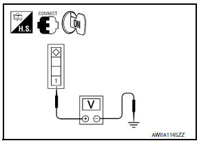
1 - Ground:Battery Voltage
2.CHECK SIGNAL FOR AIR MIX DOOR MOTOR (PASSENGER SIDE)
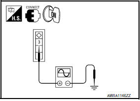
Check the output waveform (LAN signal) between air mix door motor (passenger side) harness connector M129 terminal 3 and ground using an oscilloscope.
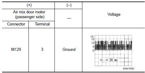
3.CHECK AIR MIX DOOR MOTOR (PASSENGER SIDE) GROUND CIRCUIT
- Turn ignition switch OFF.
- Disconnect air mix door motor (passenger side) connector.
- Check continuity between air mix door motor (passenger side) harness connector M129 terminal 2 and ground.
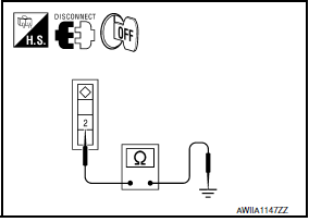
2 - Ground: Continuity should exist.
 B2632, B2633 air mix door motor (driver side)
Description
COMPONENT DESCRIPTION
Air Mix Door Motor (driver side)
The air mix door motor (driver side) (1) is attached to the heater
&
cooling unit assembly.
It rotates so that the a ...
 B2636, B2637, B2638, B2639, B2654, B2655 mode door motor
Description
COMPONENT DESCRIPTION
Mode Door Motor
The mode door motor (1) is attached to the heater & cooling unit
assembly.
It rotates so that air is discharged from the outlet set by t ...
Other materials:
Hood
HOOD ASSEMBLY
HOOD ASSEMBLY : Exploded View
Hood hinge cover (LH)
Hood stay (LH)
Hood hinge (LH)
Hood assembly
Hood bumper rubber
Seal
Hood insulator
Hood insulator clips
HOOD ASSEMBLY : Removal and Installation
CAUTION:
Use two people when removing or installi ...
Precaution
Precaution for Supplemental Restraint System (SRS) "AIR BAG" and
"SEAT BELT PRE-TENSIONER"
The Supplemental Restraint System such as "AIR BAG" and "SEAT BELT
PRE-TENSIONER", used along with a front seat belt, helps to reduce the risk
or severity of injury to the driver and front passenger for ...
Blower motor control system
System Diagram
System Description
Fan speed is automatically controlled by the temperature setting, ambient
temperature, in-vehicle temperature,
intake temperature, amount of sunload and air mix door position.
By pressing the AUTO switch, the blower motor starts to gradually increase
a ...
Nissan Maxima Owners Manual
- Illustrated table of contents
- Safety-Seats, seat belts and supplemental restraint system
- Instruments and controls
- Pre-driving checks and adjustments
- Monitor, climate, audio, phone and voice recognition systems
- Starting and driving
- In case of emergency
- Appearance and care
- Do-it-yourself
- Maintenance and schedules
- Technical and consumer information
Nissan Maxima Service and Repair Manual

0.0101