Nissan Maxima Service and Repair Manual: B2632, B2633 air mix door motor (driver side)
Description
COMPONENT DESCRIPTION
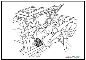
Air Mix Door Motor (driver side)
- The air mix door motor (driver side) (1) is attached to the heater & cooling unit assembly.
- It rotates so that the air mix door is opened or closed to a position set by the A/C auto amp.
- Motor rotation is then conveyed through a shaft and the air mix door position feedback is then sent to the A/C auto amp. by PBR built-in air mix door motor.
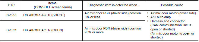
DTC Logic
DTC DETECTION LOGIC
NOTE: If DTC is displayed along with DTC U1000 or U1010, first diagnose the DTC U1000 or U1010.
DTC CONFIRMATION PROCEDURE
1.CHECK WITH SELF-DIAGNOSIS FUNCTION OF CONSULT
- Using CONSULT, perform "SELF-DIAGNOSIS RESULTS" of HVAC.
- Check if any DTC No. is displayed in the self-diagnosis results.
NOTE: If DTC is displayed along with DTC U1000 or U1010, first diagnose the DTC U1000 or U1010
2.FUNCTION INSPECTION
- Press the temperature control switch (driver side) until 32C (90F) is displayed.
- Check for warm air at discharge air outlets.
- Operate the A/C compressor.
- Press the temperature control switch (driver side) until 18C (60F) is displayed.
- Check for cool air at air discharge outlets.
Diagnosis Procedure
1.CHECK AIR MIX DOOR MOTOR (DRIVER SIDE) POWER SUPPLY
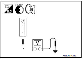
- Turn ignition switch ON.
- Check voltage between air mix door motor (driver side) harness connector M128 terminal 1 and ground.
1 - Ground: Battery Voltage
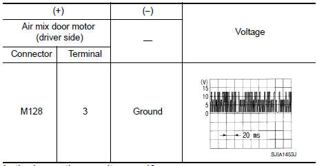
2.CHECK SIGNAL FOR AIR MIX DOOR MOTOR (DRIVER SIDE)
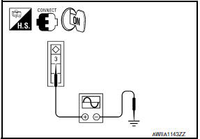
Check the output waveform (LAN signal) between air mix door motor (driver side) harness connector M128 terminal 3 and ground using an oscilloscope.
3.CHECK AIR MIX DOOR MOTOR (DRIVER SIDE) GROUND CIRCUIT
- Turn ignition switch OFF.
- Disconnect air mix door motor (driver side) connector.
- Check continuity between air mix door motor (driver side) harness connector M128 terminal 2 and ground.
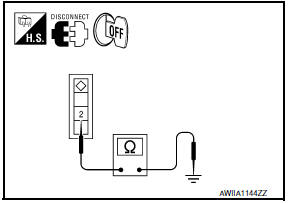
2 - Ground: Continuity should exist.
 B2630, B2631 sunload sensor
Description
COMPONENT DESCRIPTION
Sunload Sensor
The sunload sensor (1) is located on the driver side defroster
grille.
It detects sunload entering through windshield by means of a
photo ...
 B2634, B2635 air mix door motor (passenger side)
Description
COMPONENT DESCRIPTION
Air Mix Door Motor (passenger side)
The air mix door motor (passenger side) (1) is attached to the
heater & cooling unit assembly.
It rotates so that th ...
Other materials:
Difference between predicted and actual distances
The displayed guidelines and their locations on
the ground are for approximate reference only.
Objects on uphill or downhill surfaces or projecting
objects will be actually located at distances
different from those displayed in the monitor relative
to the guidelines (refer to illustrations). ...
U1000 CAN comm circuit
Description
CAN (Controller Area Network) is a serial communication
line for real time applications. It is an on-vehicle multiplex
communication line with high data communication speed and excellent error
detection ability. Modern
vehicle is equipped with many electronic control unit, and e ...
DTC/circuit diagnosis
CHARGING SYSTEM PRELIMINARY INSPECTION
Diagnosis Procedure
1.CHECK BATTERY TERMINALS CONNECTION
Check if battery terminals are clean and tight
2.CHECK FUSE
Check for blown fuse and fusible link.
3.CHECK GENERATOR GROUND TERMINAL CONNECTION
Check if connector E230 terminal 5 (generator groun ...
Nissan Maxima Owners Manual
- Illustrated table of contents
- Safety-Seats, seat belts and supplemental restraint system
- Instruments and controls
- Pre-driving checks and adjustments
- Monitor, climate, audio, phone and voice recognition systems
- Starting and driving
- In case of emergency
- Appearance and care
- Do-it-yourself
- Maintenance and schedules
- Technical and consumer information
Nissan Maxima Service and Repair Manual

0.0065