
Nissan Maxima Owners Manual: Battery replacement
CAUTION
Be careful not to allow children to swallow the battery or removed parts.
NISSAN Intelligent Key
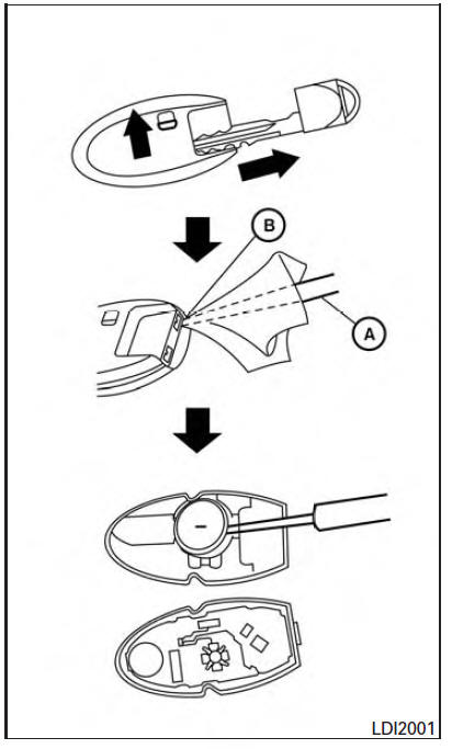
Replace the battery in the Intelligent Key as follows:
1. Remove the mechanical key from the Intelligent Key.
2. Insert a small flathead screwdriver A into the slit B of the corner and twist it to separate the upper part from the lower part. Place a cloth over the screwdriver to protect the casing.
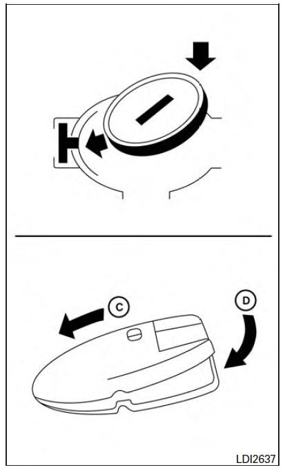
3. Replace the battery with a new one.
Recommended battery: CR2032 or equivalent.
- Do not touch the internal circuit and electric terminals as doing so could cause a malfunction.
- Hold the battery by the edges. Holding the battery across the contact points will seriously deplete the storage capacity.
- Make sure that the + side faces the bottom of the lower part.
4. Close the lid securely as illustrated with C and D .
5. Operate the buttons to check the operation.
It is recommended that you visit a NISSAN dealer if you need assistance for replacement.
FCC Notice: For USA: This device complies with Part 15 of the FCC Rules. Operation is subject to the following two conditions: (1) This device may not cause harmful interference, and (2) this device must accept any interference received, including interference that may cause undesired operation.
Note: Changes or modifications not expressly approved by the party responsible for compliance could void the user's authority to operate the equipment.
For Canada: This device complies with Industry Canada licence-exempt RSS standard(s). Operation is subject to the following two conditions: (1) this device may not cause interference, and (2) this device must accept any interference, including interference that may cause undesired operation of the device.
 Passenger compartment
WARNING
Never use a fuse of a higher or lower
amperage rating than specified on the
fuse box cover. This could damage the
electrical system or electronic control
units or cause a fire.
If an ...
 Lights
...
Other materials:
Rear sunshade
Removal and Installation
Rear sunshade unit Front
REMOVAL
Remove the rear parcel shelf finisher. Refer to INT-24, "Removal
and Installation".
Remove the rear sunshade unit.
Remove the rear sunshade unit bolts.
Disconnect the rear sunshade unit harness
connector ...
On board diagnostic (OBD) system
Trouble Diagnosis Introduction
CAUTION:
Do not use electrical test equipment on any circuit related to
the SRS unless instructed to do so inthis Service Manual. SRS wiring
harnesses can be identified by yellow and/or orange harness connectors.
Do not attempt to repair, splice or modify ...
Aux image signal circuit
Description
Transmits the image signal of AUX device from auxiliary input jacks to
AV control unit.
AV control unit transmits the image signal that is input to the
display unit.
Diagnosis Procedure
1.CHECK CONTINUITY AUX IMAGE SIGNAL CIRCUIT
Turn ignition switch OFF.
Disconnect ...
Nissan Maxima Owners Manual
- Illustrated table of contents
- Safety-Seats, seat belts and supplemental restraint system
- Instruments and controls
- Pre-driving checks and adjustments
- Monitor, climate, audio, phone and voice recognition systems
- Starting and driving
- In case of emergency
- Appearance and care
- Do-it-yourself
- Maintenance and schedules
- Technical and consumer information
Nissan Maxima Service and Repair Manual

0.02