
Nissan Maxima Service and Repair Manual: AV control unit
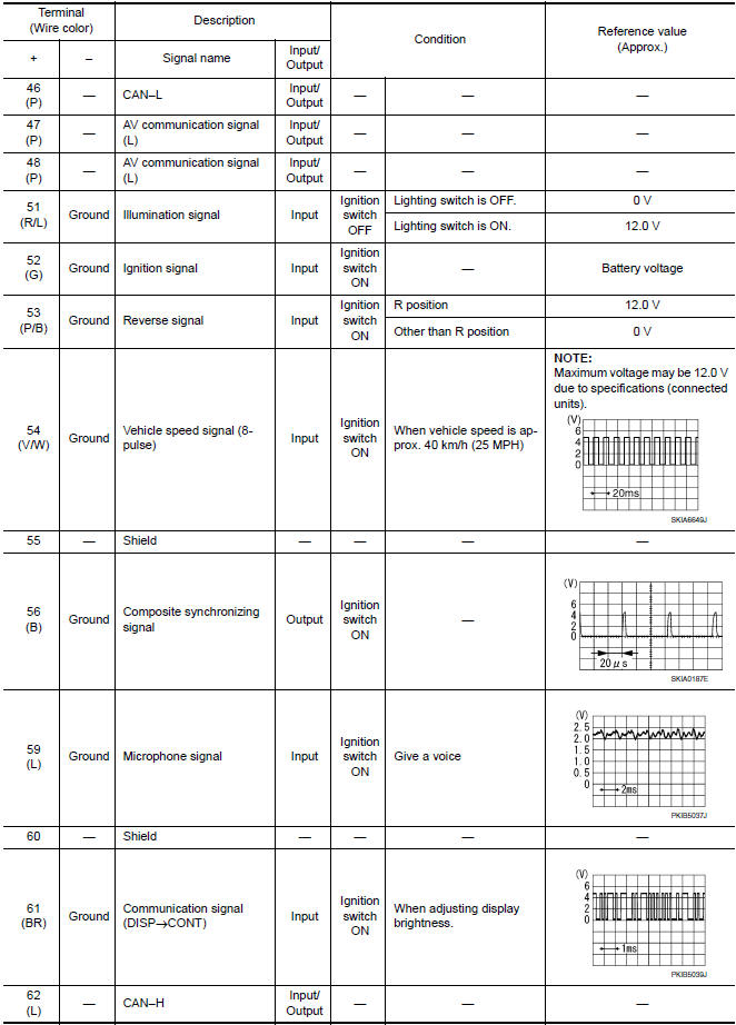
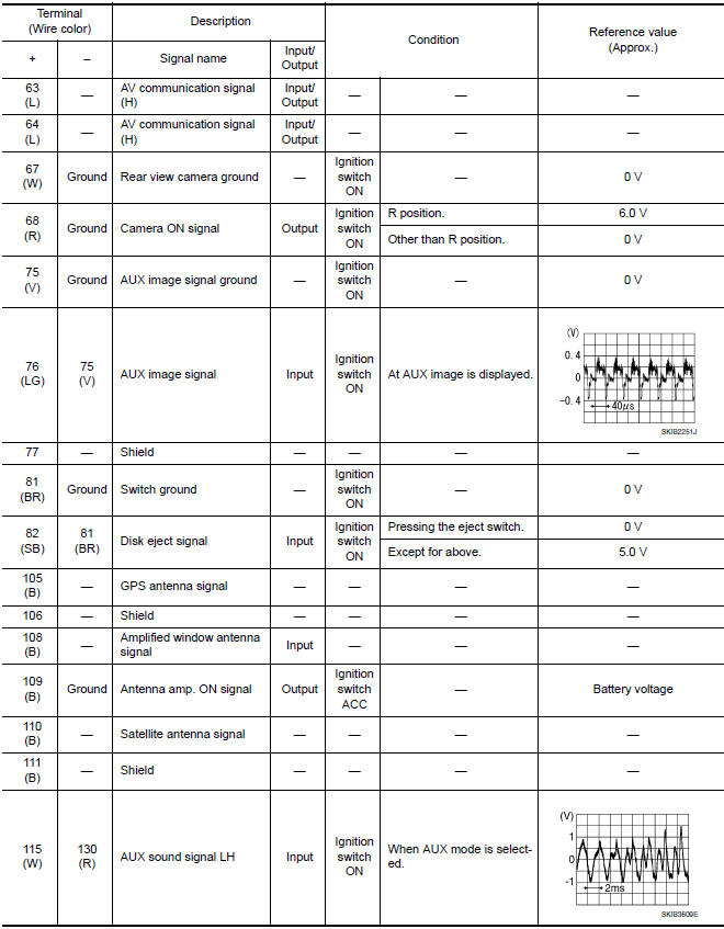
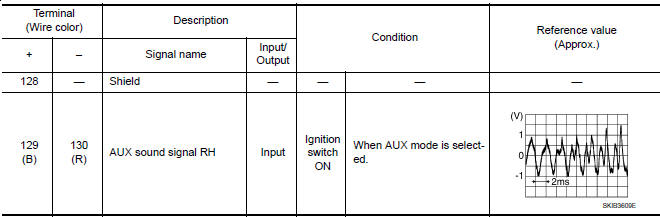
Reference Value
VALUES ON THE DIAGNOSIS TOOL
CONSULT data monitor item
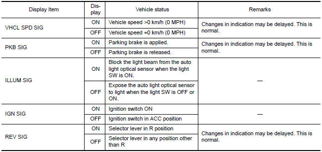
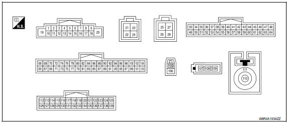
TERMINAL LAYOUT
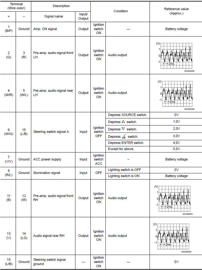
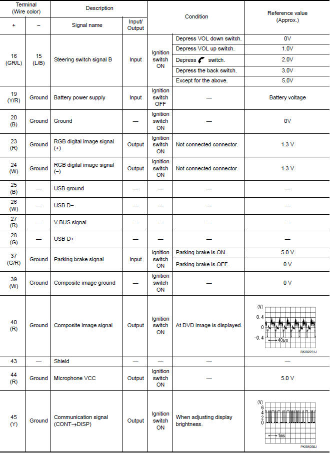
PHYSICAL VALUES
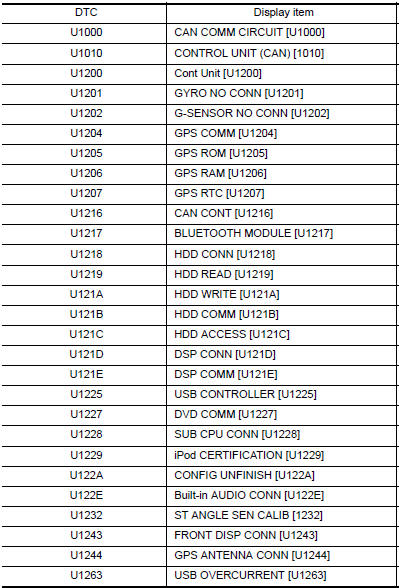
DTC Index
SELF-DIAGNOSIS RESULTS DISPLAY ITEM


 Display unit
Reference Value
TERMINAL LAYOUT
PHYSICAL VALUES
BOSE SPEAKER AMP
Reference Value
TERMINAL LAYOUT
PHYSICAL VALUES
...
Other materials:
B260f engine status
Description
BCM receives the engine status signal from ECM via CAN
communication.
DTC Logic
DTC DETECTION LOGIC
NOTE:
If DTC B260F is displayed with DTC
U1000, first perform the trouble diagnosis for DTC U1000. Refer to
SEC-29, "DTC Logic".
If DTC B260F is displayed with D ...
Compressor control function
Description
PRINCIPLE OF OPERATION
A/C compressor is not activated.
Functional circuit diagram
CAN (1): A/C switch signal
: Blower fan motor switch signal
CAN (2): A/C compressor request signal
RX: A/C switch signal
: Fan ON signal
: Defroster signal
Functional initial inspection chart ...
Auto light system
System Diagram
System Description
BCM (Body Control Module) controls auto light operation according to
signals from optical sensor, lighting switch and ignition switch.
IPDM E/R (Intelligent Power Distribution Module Engine Room) operates
parking, license plate, tail, front fog lamps ...
Nissan Maxima Owners Manual
- Illustrated table of contents
- Safety-Seats, seat belts and supplemental restraint system
- Instruments and controls
- Pre-driving checks and adjustments
- Monitor, climate, audio, phone and voice recognition systems
- Starting and driving
- In case of emergency
- Appearance and care
- Do-it-yourself
- Maintenance and schedules
- Technical and consumer information
Nissan Maxima Service and Repair Manual

0.011