Nissan Maxima Service and Repair Manual: P0011, P0021 IVT control
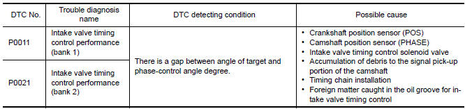
DTC Logic
DTC DETECTION LOGIC
NOTE: If DTC P0011 or P0021 is displayed with DTC P0075, P0081, first perform the trouble diagnosis for DTC P0075, P0081.
DTC CONFIRMATION PROCEDURE
1.PRECONDITIONING
If DTC Confirmation Procedure has been previously conducted, always perform the following before conducting the next test.
- Turn ignition switch OFF and wait at least 10 seconds.
- Turn ignition switch ON.
- Turn ignition switch OFF and wait at least 10 seconds.
TESTING CONDITION: Before performing the following procedure, confirm that battery voltage is between 10 V and 16 V at idle.
2.PERFORM DTC CONFIRMATION PROCEDURE-I
With CONSULT
- Turn ignition switch ON and select "DATA MONITOR" mode with CONSULT.
- Start engine and warm it up to the normal operating temperature.
- Maintain the following conditions for at least 6 consecutive seconds. Hold the accelerator pedal as steady as possible.
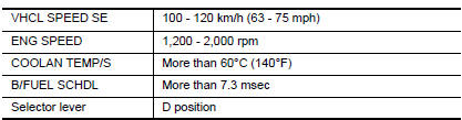
CAUTION: Always drive at a safe speed.
- Stop vehicle with engine running and let engine idle for 10 seconds.
- Check 1st trip DTC.
With GST
Follow the procedure "With CONSULT" above
3.PERFORM DTC CONFIRMATION PROCEDURE-II
With CONSULT
- Maintain the following conditions for at least 20 consecutive seconds
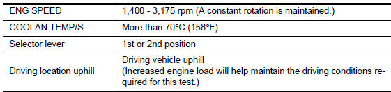
CAUTION: Always drive at a safe speed.
- Check 1st trip DTC.
With GST
Follow the procedure "With CONSULT" above.
Diagnosis Procedure
1.CHECK OIL PRESSURE WARNING LAMP
- Start engine.
- Check oil pressure warning lamp and confirm it is not illuminated.
2.CHECK INTAKE VALVE TIMING CONTROL SOLENOID VALVE
3.CHECK CRANKSHAFT POSITION SENSOR (POS)
4.CHECK CAMSHAFT POSITION SENSOR (PHASE)
5.CHECK CAMSHAFT (INTAKE)
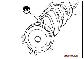
Check the following.
- Accumulation of debris on the signal plate of camshaft rear end
- Chipping signal plate of camshaft rear end
6.CHECK TIMING CHAIN INSTALLATION
Check service records for any recent repairs that may cause timing chain misalignment.
7.CHECK LUBRICATION CIRCUIT
8.CHECK INTERMITTENT INCIDENT
Component Inspection
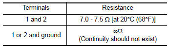
1.CHECK INTAKE VALVE TIMING CONTROL SOLENOID VALVE-I
- Disconnect intake valve timing control solenoid valve harness connector.
- Check resistance between intake valve timing control solenoid valve terminals as per the following.
2.CHECK INTAKE VALVE TIMING CONTROL SOLENOID VALVE-II
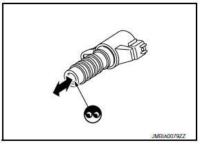
- Remove intake valve timing control solenoid valve
- Provide 12 V DC between intake valve timing control solenoid valve terminals 1 and 2, and then interrupt it. Check that the plunger moves as shown in the figure.
CAUTION: Never apply 12 V DC continuously for 5 seconds or more.
Doing so may result in damage to the coil in intake valve timing control solenoid valve.
NOTE: Always replace O-ring when intake valve timing control solenoid valve is removed.
 U1001 can comm circuit
Description
CAN (Controller Area Network) is a serial communication line for real time
application. It is an on-vehicle multiplex
communication line with high data communication speed and excelle ...
 P0014, P0024 EVT control
DTC Logic
DTC DETECTION LOGIC
NOTE:
If DTC P0014 or P0024 is displayed with DTC P0078, P0084 first
perform trouble diagnosis for DTC
P0078, P0084. Refer to EC-180, "DTC Logic&qu ...
Other materials:
B2553 ignition relay
Description
BCM turns ON the following relays to ignition power supply to each ECU when
the ignition switch is turned
ON.
Ignition relay-1 (inside IPDM E/R)
Ignition relay-2 (inside fuse block (J/B))
Front blower motor relay
BCM checks any ignition relay ON request for consistency wi ...
Service data and specifications (SDS)
SERVICE DATA AND SPECIFICATIONS (SDS)
General Specifications
Brake Pedal
Check Valve
Brake Booster
Front Disc Brake
Rear Disc Brake
...
P1740 select solenoid
Description
The lock-up select solenoid valve controls
lock-up clutch pressure or forward clutch pressure (reverse brake
pressure).
When controlling lock-up clutch, the valve is
turned OFF. When controlling forward clutch, it is turned ON.
DTC Logic
DTC DET ...
Nissan Maxima Owners Manual
- Illustrated table of contents
- Safety-Seats, seat belts and supplemental restraint system
- Instruments and controls
- Pre-driving checks and adjustments
- Monitor, climate, audio, phone and voice recognition systems
- Starting and driving
- In case of emergency
- Appearance and care
- Do-it-yourself
- Maintenance and schedules
- Technical and consumer information
Nissan Maxima Service and Repair Manual

0.0059