Nissan Maxima Service and Repair Manual: B263D, B263E, B263f intake door motor
Description
COMPONENT DESCRIPTION
Intake Door Motor
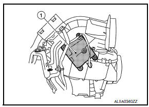
- The intake door motor (1) is attached to the blower unit.
- It rotates so that air is drawn from inlets set by the A/C auto
amp.
Motor rotation is conveyed to a lever which activates the intake door.
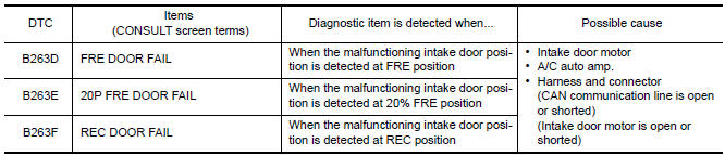
DTC Logic
DTC DETECTION LOGIC
NOTE: If DTC is displayed along with DTC U1000 or U1010, first diagnose the DTC U1000 or U1010.
DTC CONFIRMATION PROCEDURE
1.CHECK WITH SELF-DIAGNOSIS FUNCTION OF CONSULT
- Using CONSULT, perform "SELF-DIAGNOSIS RESULTS" of HVAC.
- Check if any DTC No. is displayed in the self-diagnosis results.
NOTE: If DTC is displayed along with DTC U1000 or U1010, first diagnose the DTC U1000 or U1010.
2.FUNCTION INSPECTION
- Press the REC (
 )
switch, indicator is turned ON.
)
switch, indicator is turned ON. - Listen for intake door position change. (Slight change of blower sound can be heard.)
- Press the FRE (
 )
switch, indicator is turned ON.
)
switch, indicator is turned ON. - Listen for intake door position change. (Slight change of blower sound can be heard.)
Diagnosis Procedure
1.CHECK INTAKE DOOR MOTOR POWER SUPPLY
- Turn ignition switch ON.
- Check voltage between intake door motor harness connector M126 terminal 1 and ground.
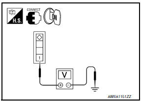
1 - Ground: Battery Voltage
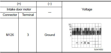
2.CHECK SIGNAL FOR INTAKE DOOR MOTOR
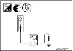
Confirm A/C LAN signal between intake door motor harness connector M126 terminal 3 and ground using an oscilloscope.
3.CHECK INTAKE DOOR MOTOR GROUND CIRCUIT
- Turn ignition switch OFF.
- Disconnect intake door motor connector.
- Check continuity between intake door motor harness connector M126 terminal 2 and ground.
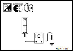
2 - Ground: Continuity should exist.
 B2636, B2637, B2638, B2639, B2654, B2655 mode door motor
Description
COMPONENT DESCRIPTION
Mode Door Motor
The mode door motor (1) is attached to the heater & cooling unit
assembly.
It rotates so that air is discharged from the outlet set by t ...
 Blower motor
Description
COMPONENT DESCRIPTION
Brush-less Motor
The blower motor utilizes a brush-less motor with a rotating magnet.
Quietness is improved over previous motors where the brush was
the point ...
Other materials:
Combination meter
Reference Value
VALUES ON THE DIAGNOSIS TOOL
NOTE:
* The monitor will indicate "OFF" even though
the brake warning lamp is on if either of the following conditions exist:
The parking brake is engaged
The brake fluid level is low
TERMINAL LAYOUT
PHYSICAL VALUES
...
Drive mode selector
Drive mode selector switches
Two driving modes can be selected by using the
drive mode selector switches, NORMAL and
SPORT.
NOTE:
When the drive mode select switch selects a
mode, the mode may not switch quickly. This
is not a malfunction.
Select the NORMAL mode for normal driving. ...
Towing your vehicle
When towing your vehicle, all State (Provincial in
Canada) and local regulations for towing must be
followed. Incorrect towing equipment could damage
your vehicle. Towing instructions are available
from a NISSAN dealer. Local service operators
are generally familiar with the applicable laws
an ...
Nissan Maxima Owners Manual
- Illustrated table of contents
- Safety-Seats, seat belts and supplemental restraint system
- Instruments and controls
- Pre-driving checks and adjustments
- Monitor, climate, audio, phone and voice recognition systems
- Starting and driving
- In case of emergency
- Appearance and care
- Do-it-yourself
- Maintenance and schedules
- Technical and consumer information
Nissan Maxima Service and Repair Manual

0.0055