Nissan Maxima Service and Repair Manual: B2636, B2637, B2638, B2639, B2654, B2655 mode door motor
Description
COMPONENT DESCRIPTION
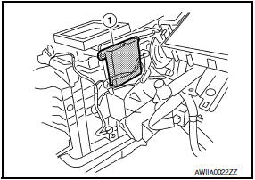
Mode Door Motor
- The mode door motor (1) is attached to the heater & cooling unit assembly.
- It rotates so that air is discharged from the outlet set by the A/C auto amp. Motor rotation is conveyed to a link which activates the mode door
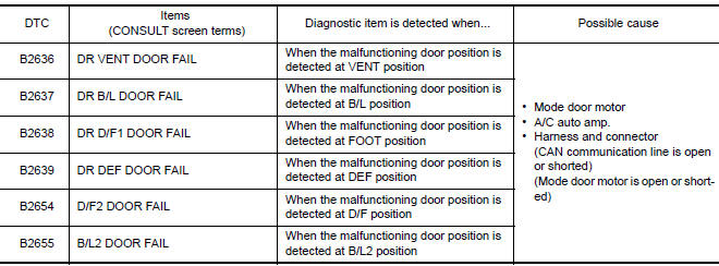
DTC Logic
DTC DETECTION LOGIC
NOTE: If DTC is displayed along with DTC U1000 or U1010, first diagnose the DTC U1000 or U1010.
DTC CONFIRMATION PROCEDURE
1.CHECK WITH SELF-DIAGNOSIS FUNCTION OF CONSULT
- Using CONSULT, perform "SELF-DIAGNOSIS RESULTS" of HVAC.
- Check if any DTC No. is displayed in the self-diagnosis results.
NOTE: If DTC is displayed along with DTC U1000 or U1010, first diagnose the DTC U1000 or U1010.
2.FUNCTION INSPECTION
- Press MODE switch and DEF switch.
- Each position indicator should change shape.
- Confirm that air discharge comes out according to the air distribution table. Refer to HAC-9, "Description".
NOTE: Confirm that the compressor clutch is engaged (sound
or visual inspection) and intake door position is at FRE
(  ) when DEF (
 ) or D/F (
 ) is selected.
Diagnosis Procedure
1.CHECK MODE DOOR MOTOR POWER SUPPLY
- Turn ignition switch ON.
- Check voltage between mode door motor harness connector M127 terminal 1 and ground.
1 - Ground: Battery Voltage
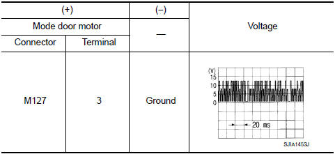
2.CHECK SIGNAL FOR MODE DOOR MOTOR
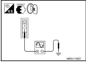
Confirm A/C LAN signal between mode door motor harness connector M127 terminal 3 and ground using an oscilloscope.
3.CHECK MODE DOOR MOTOR GROUND CIRCUIT
- Turn ignition switch OFF.
- Disconnect mode door motor connector.
- Check continuity between mode door motor harness connector M127 terminal 2 and ground.
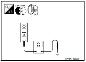
2- Ground: Continuity should exist.
 B2634, B2635 air mix door motor (passenger side)
Description
COMPONENT DESCRIPTION
Air Mix Door Motor (Passenger Side)
The air mix door motor (passenger side) (1) is attached to the
heater & cooling unit assembly.
It rotates so that th ...
 B263D, B263E, B263f intake door motor
Description
COMPONENT DESCRIPTION
Intake Door Motor
The intake door motor (1) is attached to the blower unit.
It rotates so that air is drawn from inlets set by the A/C auto
amp.
Motor ...
Other materials:
Precautions
Precaution for Supplemental Restraint System (SRS) "AIR BAG" and "SEAT
BELT
PRE-TENSIONER"
The Supplemental Restraint System such as "AIR BAG" and "SEAT BELT
PRE-TENSIONER", used along
with a front seat belt, helps to reduce the risk or severity of injury to the
driver ...
Windshield glass
Exploded View
Windshield glass
Spacer
Mirror base
Adhesive
Primer
Windshield molding
Metal roof
Dual Panel Sunroof
Front pillar
Cowl top
Rubber dam G.
16 mm (0.63 in) for top and sides 25 mm
(0.98 in) for bottom
12 + 2, - 0 mm (0.47 + 0.08 - 0 in)
&n ...
Power supply and ground circuit
BCM
BCM : Diagnosis Proce
1. CHECK FUSE AND FUSIBLE LINK
Check if the following BCM fuses or fusible link are blow
2. CHECK POWER SUPPLY CIRCUIT
Turn ignition switch OFF.
Disconnect BCM.
Check voltage between BCM harness connector and ground.
3. CHECK GROUND CIRCUIT
Check con ...
Nissan Maxima Owners Manual
- Illustrated table of contents
- Safety-Seats, seat belts and supplemental restraint system
- Instruments and controls
- Pre-driving checks and adjustments
- Monitor, climate, audio, phone and voice recognition systems
- Starting and driving
- In case of emergency
- Appearance and care
- Do-it-yourself
- Maintenance and schedules
- Technical and consumer information
Nissan Maxima Service and Repair Manual

0.0066