Nissan Maxima Service and Repair Manual: B2634, B2635 air mix door motor (passenger side)
Description
COMPONENT DESCRIPTION
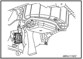
Air Mix Door Motor (Passenger Side)
- The air mix door motor (passenger side) (1) is attached to the heater & cooling unit assembly.
- It rotates so that the air mix door is opened or closed to a position set by the A/C auto amp.
- Motor rotation is then conveyed through a shaft and the air mix door position feedback is then sent to the A/C auto amp. by PBR built-in air mix door motor.
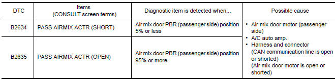
DTC Logic
DTC DETECTION LOGIC
NOTE: If DTC is displayed along with DTC U1000 or U1010, first diagnose the DTC U1000 or U1010.
DTC CONFIRMATION PROCEDURE
1.CHECK WITH SELF-DIAGNOSIS FUNCTION OF CONSULT
- Using CONSULT, perform "SELF-DIAGNOSIS RESULTS" of HVAC.
- Check if any DTC No. is displayed in the self-diagnosis results.
NOTE: If DTC is displayed along with DTC U1000 or U1010, first diagnose the DTC U1000 or U1010.
2.FUNCTION INSPECTION
- Turn the temperature control dial (passenger side) until 32C (90F) is displayed.
- Check for warm air at discharge air outlets.
- Operate the compressor.
- Turn the temperature control dial (passenger side) until 18C (60F) is displayed.
- Check for cool air at air discharge outlets.
Diagnosis Procedure
1.CHECK AIR MIX DOOR MOTOR (PASSENGER SIDE) POWER SUPPLY
- Turn ignition switch ON.
- Check voltage between air mix door motor (passenger side) harness connector M129 terminal 1 and ground.
1 - Ground:Battery Voltage
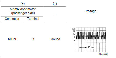
2.CHECK SIGNAL FOR AIR MIX DOOR MOTOR (PASSENGER SIDE)
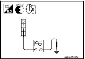
Check the output waveform (LAN signal) between air mix door motor (passenger side) harness connector and ground using an oscilloscope.
3.CHECK AIR MIX DOOR MOTOR (PASSENGER SIDE) GROUND CIRCUIT
- Turn ignition switch OFF.
- Disconnect air mix door motor (passenger side) connector.
- Check continuity between air mix door motor (passenger side) harness connector M129 terminal 2 and ground.
2 - Ground: Continuity should exist.
 B2632, B2633 air mix door motor (driver side)
Description
COMPONENT DESCRIPTION
Air Mix Door Motor (Driver side)
The air mix door motor (driver side) (1) is attached to the heater
&
cooling unit assembly.
It rotates so that the a ...
 B2636, B2637, B2638, B2639, B2654, B2655 mode door motor
Description
COMPONENT DESCRIPTION
Mode Door Motor
The mode door motor (1) is attached to the heater & cooling unit
assembly.
It rotates so that air is discharged from the outlet set by t ...
Other materials:
C1109 battery voltage [abnormal]
Description
Supplies electric power to the ABS actuator and electric unit (control unit).
DTC Logic
DTC DETECTION LOGIC
DTC CONFIRMATION PROCEDURE
1.CHECK SELF-DIAGNOSIS RESULTS
Check the self-diagnosis results.
Diagnosis Procedure
1.CONNECTOR INSPECTION
Turn ignition switch OFF. ...
Power outlet
Console Box
The power outlet is for powering electrical accessories
such as cellular telephones. It is rated at
12 volt, 120W (10A) maximum.
The power outlet is powered only when the ignition
switch is in the ACC or ON position.
CAUTION
The outlet and plug may be hot during
or immedi ...
Front tweeter
Removal and Installation
REMOVAL
Remove the front pillar finisher. Refer to IP-10, "Exploded View".
Remove the front tweeter speaker grille. Refer to IP-10, "Exploded
View".
Remove the front tweeter speaker screws (A).
Pull out front tweeter speaker (1), disconnect the harness
con ...
Nissan Maxima Owners Manual
- Illustrated table of contents
- Safety-Seats, seat belts and supplemental restraint system
- Instruments and controls
- Pre-driving checks and adjustments
- Monitor, climate, audio, phone and voice recognition systems
- Starting and driving
- In case of emergency
- Appearance and care
- Do-it-yourself
- Maintenance and schedules
- Technical and consumer information
Nissan Maxima Service and Repair Manual

0.0065