Nissan Maxima Service and Repair Manual: ABS branch line circuit
Diagnosis Procedure
1.CHECK CONNECTOR
- Turn the ignition switch OFF.
- Disconnect the battery cable from the negative terminal.
- Check the terminals and connectors of the ABS actuator and electric unit (control unit) for damage, bend and loose connection (unit side and connector side).
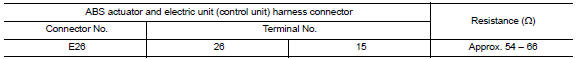
2.CHECK HARNESS FOR OPEN CIRCUIT
- Disconnect the connector of ABS actuator and electric unit (control unit).
- Check the resistance between the ABS actuator and electric unit (control unit) harness connector terminals.
3.CHECK POWER SUPPLY AND GROUND CIRCUIT
Check the power supply and the ground circuit of the ABS actuator and electric unit (control unit). Refer to BRC-83, "Wiring Diagram".
 A-bag branch line circuit
Diagnosis Procedure
WARNING:
Always observe the following items for preventing accidental
activation.
- Before servicing, turn ignition switch OFF, disconnect battery negative
terminal, and w ...
 TCM branch line circuit
Diagnosis Procedure
1.CHECK CONNECTOR
Turn the ignition switch OFF.
Disconnect the battery cable from the negative terminal.
Check the following terminals and connectors for damage, bend and ...
Other materials:
B2615 front blower motor relay circuit
Description
BCM controls the various electrical components and simultaneously supplies
power according to the power
supply position.
BCM checks the power supply position internally.
DTC Logic
DTC DETECTION LOGIC
DTC CONFIRMATION PROCEDURE
1. PERFORM DTC CONFIRMATION PROCEDURE
Tur ...
B1XXX air bag diagnosis sensor unit
Description
DTC B1XXX AIR BAG DIAGNOSIS SENSOR UNIT
The air bag diagnosis sensor unit will run self diagnostics when the ignition
switch is turned ON. It has thepotential to set many diagnostic trouble
codes which will conform to the B1XXX format, but will not match anyother
SRS diagnostic t ...
B terminal C
Description
The "B" terminal is constantly supplied with battery power.
Diagnosis Procedure
CAUTION: Perform diagnosis under the condition that
the engine cannot start by the following procedure.
Remove fuel pump fuse.
Crank or start the engine (where possible) unt ...
Nissan Maxima Owners Manual
- Illustrated table of contents
- Safety-Seats, seat belts and supplemental restraint system
- Instruments and controls
- Pre-driving checks and adjustments
- Monitor, climate, audio, phone and voice recognition systems
- Starting and driving
- In case of emergency
- Appearance and care
- Do-it-yourself
- Maintenance and schedules
- Technical and consumer information
Nissan Maxima Service and Repair Manual

0.006