Nissan Maxima Service and Repair Manual: Remote keyless entry receiver
Description
Receives Intelligent Key operation and transmits to BCM.
Component Function Check
1. CHECK FUNCTION
With CONSULT
Check remote keyless entry receiver RKE OPE COUN1 in Data Monitor mode with CONSULT

Diagnosis Procedure
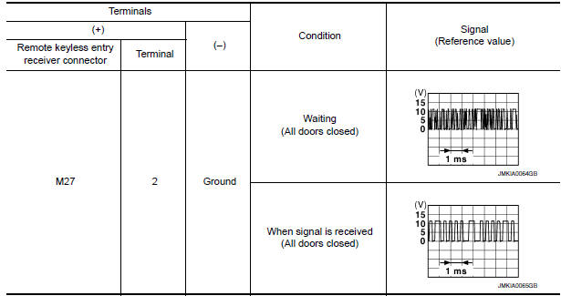
1. CHECK REMOTE KEYLESS ENTRY RECEIVER OUTPUT SIGNAL
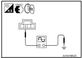
- Turn ignition switch OFF.
- Check signal between remote keyless entry receiver connector and ground with oscilloscope.
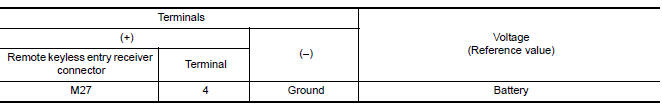
2. CHECK REMOTE KEYLESS ENTRY RECEIVER POWER SUPPLY
- Disconnect remote keyless entry receiver connector.
- Check voltage between remote keyless entry receiver connector and ground.
3. CHECK REMOTE KEYLESS ENTRY RECEIVER CIRCUIT 1
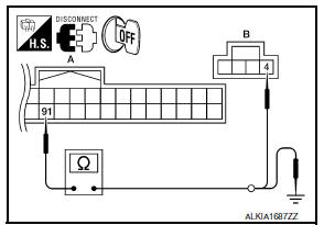
- Disconnect BCM connector.
- Check continuity between BCM connector and remote keyless entry receiver connector
- Check continuity between BCM connector and ground.
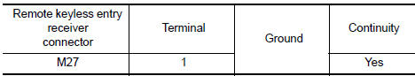
4. CHECK REMOTE KEYLESS ENTRY RECEIVER GROUND CIRCUIT
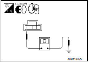
Check continuity between remote keyless entry receiver connector and ground.
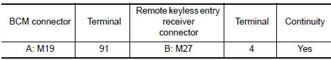
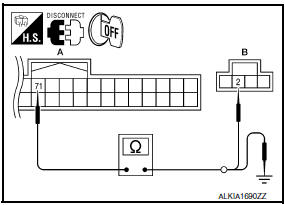
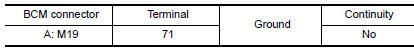
5. CHECK REMOTE KEYLESS ENTRY RECEIVER CIRCUIT 2
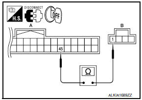
Check continuity between BCM connector and remote keyless entry receiver connector.
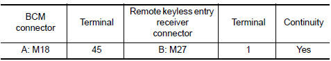
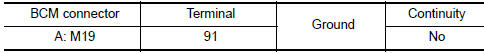
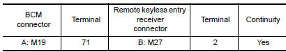
6. CHECK REMOTE KEYLESS ENTRY RECEIVER CIRCUIT 3
- Check continuity between BCM connector and remote keyless entry receiver connector
- Check continuity between BCM connector and ground.
7. CHECK INTERMITTENT INCIDENT
 Outside key antenna
Description
Detects whether Intelligent Key is outside the vehicle.
Integrated in front outside handle (driver side, passenger side) and installed
in rear bumper.
Component Function Check
NO ...
 Intelligent key
Description
The following functions are available when having and carrying the
Intelligent Key.
Door lock/unlock
Trunk open
Remote control entry function and panic alarm function are avai ...
Other materials:
Rear window and outside mirror (if so equipped) defroster switch
To defrost the rear window glass and outside
mirror (if so equipped), start the engine and push
the rear window defroster switch on. The rear
window defroster indicator light on the switch
comes on. Push the switch again to turn the
defroster off.
The rear window defroster automatically ...
Difference between predicted and actual distances
The displayed guidelines and their locations on
the ground are for approximate reference only.
Objects on uphill or downhill surfaces or projecting
objects will be actually located at distances
different from those displayed in the monitor relative
to the guidelines (refer to illustrations). ...
U1010 control unit (CAN)
Description
CAN (Controller Area Network) is a serial communication line for real time
application. It is an on-vehicle multiplex
communication line with high data communication speed and excellent malfunction
detection ability.
Many electronic control units are equipped onto a vehicle, an ...
Nissan Maxima Owners Manual
- Illustrated table of contents
- Safety-Seats, seat belts and supplemental restraint system
- Instruments and controls
- Pre-driving checks and adjustments
- Monitor, climate, audio, phone and voice recognition systems
- Starting and driving
- In case of emergency
- Appearance and care
- Do-it-yourself
- Maintenance and schedules
- Technical and consumer information
Nissan Maxima Service and Repair Manual

0.0054