Nissan Maxima Service and Repair Manual: Tilt sensor
Description
- The tilt sensor is installed to the steering column assembly.
- The pulse signal is input to the driver seat control unit when the tilt is operated.
- The driver seat control unit counts the pulse and calculates the tilt amount of the steering column.
Component Function Check
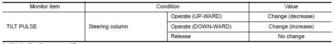
1.CHECK FUNCTION
- Select "TILT PULSE" in "DATA MONITOR" mode with CONSULT.
- Check tilt sensor signal under the following conditions.
Diagnosis Procedure
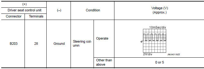
1. CHECK TILT SENSOR SIGNAL
- Turn ignition switch ON.
- Check voltage signal between driver seat control unit connector and ground with oscilloscope.
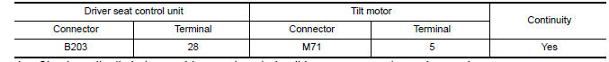
2. CHECK TILT SENSOR CIRCUIT
- Turn ignition switch OFF.
- Disconnect driver seat control unit and tilt motor.
- Check continuity between driver seat control unit harness connector and tilt motor harness connector.
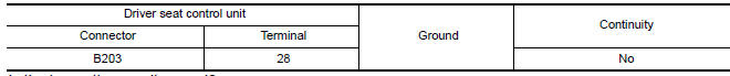
- Check continuity between driver seat control unit harness connector and ground.
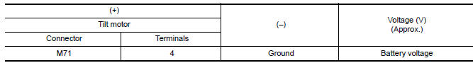
3. CHECK TILT SENSOR POWER SUPPLY
- Connect driver seat control unit.
- Turn ignition switch ON.
- Check voltage between tilt motor harness connector and ground.
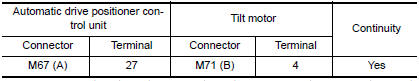
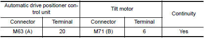
4. CHECK TILT SENSOR POWER SUPPLY CIRCUIT
- Turn ignition switch OFF.
- Disconnect automatic drive positioner control unit.
- Check continuity between automatic drive positioner control unit harness connector and tilt motor harness connector.
- Check continuity between automatic drive positioner control unit harness connector and ground.

5. CHECK TILT SENSOR GROUND CIRCUIT
- Turn ignition switch OFF.
- Disconnect automatic drive positioner control unit.
- Check continuity between automatic drive positioner control unit harness connector and tilt motor harness connector.
 Lifting sensor (rear)
Description
The lifting sensor (rear) is installed to the seat frame.
The pulse signal is input to the driver seat control unit when the
lifting (rear) is operated.
The driver seat control ...
 Telescopic sensor
Description
The telescopic sensor is installed to the steering column assembly.
The pulse signal is input to the driver seat control unit when
telescopic is performed.
The driver seat contr ...
Other materials:
ECM branch line circuit
Diagnosis Procedure
1.CHECK CONNECTOR
Turn the ignition switch OFF.
Disconnect the battery cable from the negative terminal.
Check the following terminals and connectors for damage, bend and
loose connection (unit side and connector
side).
- Models without automatic drive positione ...
Cleaning
If your windshield is not clear after using the
windshield-washer or if a wiper blade chatters
when running, wax or other material may be on
the blade or windshield.
Clean the outside of the windshield with a washer
solution or a mild detergent. Your windshield is
clean if beads do not form ...
Diagnosis system (bluetooth control unit)
Diagnosis Description
The Bluetooth control unit has two diagnostic checks. The first diagnostic
check is performed automatically every ignition cycle during control unit
initialization. The second diagnostic check is performed by the technician
using the steering wheel audio control switches ...
Nissan Maxima Owners Manual
- Illustrated table of contents
- Safety-Seats, seat belts and supplemental restraint system
- Instruments and controls
- Pre-driving checks and adjustments
- Monitor, climate, audio, phone and voice recognition systems
- Starting and driving
- In case of emergency
- Appearance and care
- Do-it-yourself
- Maintenance and schedules
- Technical and consumer information
Nissan Maxima Service and Repair Manual

0.0055