Nissan Maxima Service and Repair Manual: Lifting sensor (rear)
Description
- The lifting sensor (rear) is installed to the seat frame.
- The pulse signal is input to the driver seat control unit when the lifting (rear) is operated.
- The driver seat control unit counts the pulse and calculates the lifting (rear) amount of the seat.
Component Function Check
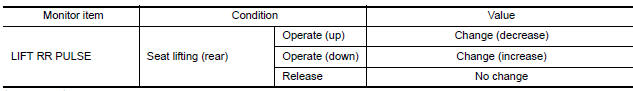
1. CHECK FUNCTION
- Select "LIFT RR PULSE" in "DATA MONITOR" mode with CONSULT.
- Check lifting sensor (rear) signal under the following conditions
Diagnosis Procedure
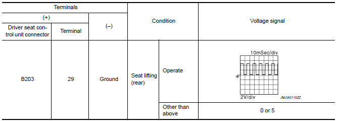
1. CHECK LIFTING SENSOR (REAR) SIGNAL
- Turn ignition switch ON.
- Read voltage signal between driver seat control unit harness connector and ground with oscilloscope.
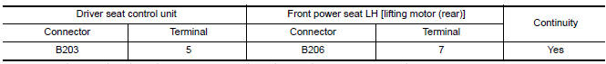
2. CHECK LIFTING SENSOR (REAR) CIRCUIT
- Turn ignition switch OFF.
- Disconnect driver seat control unit and front power seat LH [lifting motor (rear)].
- Check the continuity between driver seat control unit harness connector and front power seat LH [lifting motor (rear)] harness connector.

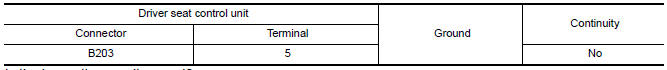
- Check the continuity between driver seat control unit harness connector and ground.

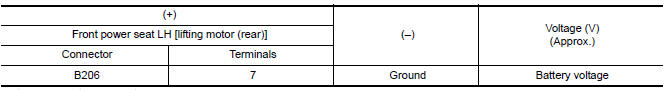
3. CHECK LIFTING SENSOR (REAR) POWER SUPPLY
- Connect driver seat control unit.
- Turn ignition switch ON.
- Check the voltage between front power seat LH [lifting motor (rear)] harness connector and ground.
4. CHECK LIFTING SENSOR (REAR) POWER SUPPLY CIRCUIT
- Turn ignition switch OFF.
- Disconnect driver seat control unit.
- Check the continuity between driver seat control unit harness connector and front power seat LH [lifting motor (rear)] harness connector
- Check the continuity between driver seat control unit harness connector and ground.
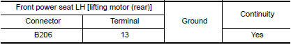
5. CHECK LIFTING SENSOR (REAR) GROUND
- Turn ignition switch OFF.
- Check the continuity between front power seat LH [lifting motor (rear)] harness connector and ground.
 Lifting sensor (front)
Description
The lifting sensor (front) is installed to the seat frame.
The pulse signal is input to the driver seat control unit when the
lifting (front) is operated.
The driver seat contro ...
 Tilt sensor
Description
The tilt sensor is installed to the steering column assembly.
The pulse signal is input to the driver seat control unit when the tilt
is operated.
The driver seat control unit c ...
Other materials:
Horizontal synchronizing (HP) signal circuit
Description
In composite image (AUX image, camera image), transmit the vertical
synchronizing (VP) signal and horizontal
synchronizing (HP) signal from display unit to AV control unit so as to
synchronize the RGB images displayed
with AV control unit such as the image quality adjusting menu ...
Steering knuckle
Removal and Installation
Steering knuckle
Splash guard
Wheel hub and bearing
Cotter pin
REMOVAL
Remove the front wheel hub and bearing. Refer to FAX-7, "Removal
and Installation".
Remove the steering linkage from the steering knuckle. Refer to
ST-26, "Removal and Insta ...
Diagnosis and repair workflow
Work Flow
OVERALL SEQUENCE
DETAILED FLOW\
1.CHECK SYMPTOM
Check the malfunction symptoms by performing the following items.
Interview the customer to obtain the malfunction information
(conditions and environment when the malfunction occurred).
Check the symptom.
2.SELF-DIAGNOSIS ( ...
Nissan Maxima Owners Manual
- Illustrated table of contents
- Safety-Seats, seat belts and supplemental restraint system
- Instruments and controls
- Pre-driving checks and adjustments
- Monitor, climate, audio, phone and voice recognition systems
- Starting and driving
- In case of emergency
- Appearance and care
- Do-it-yourself
- Maintenance and schedules
- Technical and consumer information
Nissan Maxima Service and Repair Manual

0.0082