Nissan Maxima Service and Repair Manual: Lifting sensor (front)
Description
- The lifting sensor (front) is installed to the seat frame.
- The pulse signal is input to the driver seat control unit when the lifting (front) is operated.
- The driver seat control unit counts the pulse and calculates the lifting (front) amount of the seat.
Component Function Check
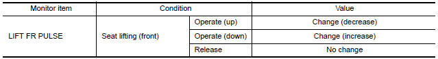
1.CHECK FUNCTION
- Select "LIFT FR PULSE" in "DATA MONITOR" mode with CONSULT.
- Check the lifting sensor (front) signal under the following conditions.
Diagnosis Procedure
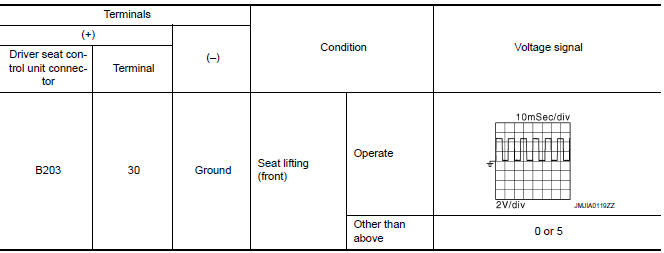
1. CHECK LIFTING SENSOR (FRONT) SIGNAL
- Turn ignition switch ON.
- Read the voltage signal between driver seat control unit harness connector and ground with an oscilloscope.
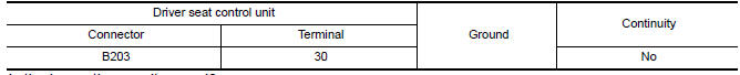
2. CHECK LIFTING SENSOR (FRONT) CIRCUIT
- Turn ignition switch OFF.
- Disconnect driver seat control unit and front power seat LH [lifting motor (front)].
- Check continuity between driver seat control unit harness connector and front power seat LH [lifting motor (front)] harness connector.

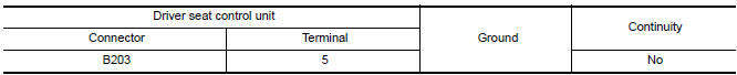
- Check continuity between driver seat control unit harness connector and ground.
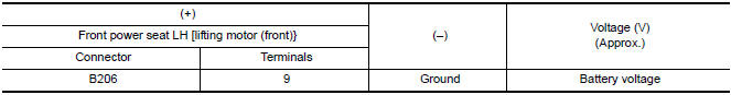
3. CHECK LIFTING SENSOR (FRONT) POWER SUPPLY
- Connect driver seat control unit.
- Turn ignition switch ON.
- Check voltage between front power seat LH [lifting motor (front)] harness connector and ground.
4. CHECK LIFTING SENSOR (FRONT) POWER SUPPLY CIRCUIT
- Turn ignition switch OFF.
- Disconnect driver seat control unit.
- 3. Check continuity between driver seat control unit harness connector and front power seat LH [lifting motor (front)] harness connector.

- Check continuity between driver seat control unit harness connector and ground.
5. CHECK LIFTING SENSOR (FRONT) GROUND
- Turn ignition switch OFF.
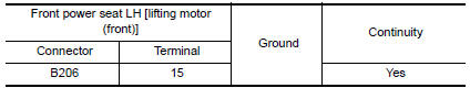
- Check continuity between front power seat LH [lifting motor (front)] harness connector and ground.
 Reclining sensor
Description
The reclining motor is installed to the seatback assembly.
The pulse signal is input to the driver seat control unit when the
reclining is operated.
The driver seat control unit ...
 Lifting sensor (rear)
Description
The lifting sensor (rear) is installed to the seat frame.
The pulse signal is input to the driver seat control unit when the
lifting (rear) is operated.
The driver seat control ...
Other materials:
Tire equipment
1. SUMMER tires have a tread designed to
provide superior performance on dry pavement.
However, the performance of these
tires will be substantially reduced in snowy
and icy conditions. If you operate your vehicle
on snowy or icy roads, NISSAN recommends
the use of MUD & SNOW or ALL
SEA ...
Air mix door control system
System Diagram
System Description
The air mix doors are automatically controlled so that in-vehicle temperature
is maintained at a predetermined
value by the temperature setting, ambient temperature, intake temperature and
amount of sunload.
SYSTEM OPERATION
The A/C auto amp. receive ...
B210C starter control relay
DTC Logic
DTC DETECTION LOGIC
NOTE:
If DTC B210C is displayed with DTC
U1000, first perform the trouble diagnosis for DTC U1000. Refer to
SEC-29, "DTC Logic".
If DTC B210C is displayed with DTC
U1010, first perform the trouble diagnosis for DTC U1010. Refer to
SEC-30, "D ...
Nissan Maxima Owners Manual
- Illustrated table of contents
- Safety-Seats, seat belts and supplemental restraint system
- Instruments and controls
- Pre-driving checks and adjustments
- Monitor, climate, audio, phone and voice recognition systems
- Starting and driving
- In case of emergency
- Appearance and care
- Do-it-yourself
- Maintenance and schedules
- Technical and consumer information
Nissan Maxima Service and Repair Manual

0.0062