Nissan Maxima Service and Repair Manual: Door request switch
Description
Transmits door lock/unlock operation to BCM.
Component Function Check
1. CHECK FUNCTION
With CONSULT
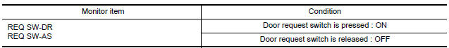
Check door request switch REQ SW-DR, REQ SW-AS in Data Monitor mode.
Diagnosis Procedure
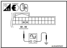
1. CHECK DOOR REQUEST SWITCH OUTPUT SIGNAL
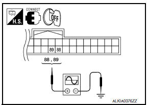
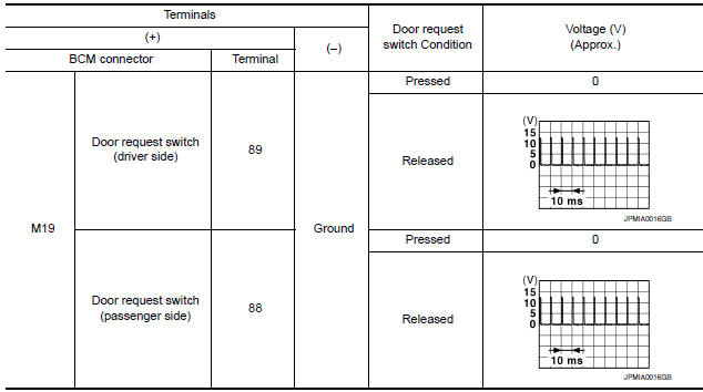
- Turn ignition switch OFF.
- Check voltage between BCM harness connector and ground.
2. CHECK DOOR REQUEST SWITCH CIRCUIT
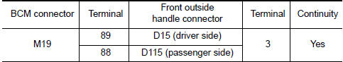
- Disconnect BCM and front outside handle connector.
- Check continuity between BCM connector and front outside handle connector.
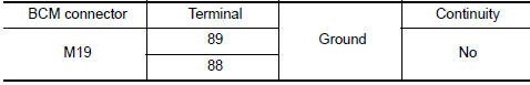
- Check continuity between BCM connector and ground.
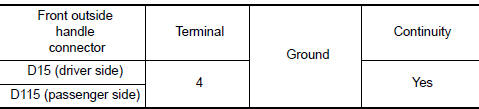
3. CHECK DOOR REQUEST SWITCH GROUND CIRCUIT
Check continuity between front outside handle connector and ground.
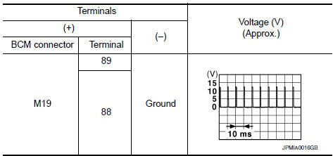
4. CHECK BCM OUTPUT SIGNAL
- Connect BCM connector.
- Check voltage between BCM connector and ground.
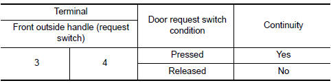
5. CHECK DOOR REQUEST SWITCH
6. CHECK INTERMITTENT INCIDENT
Component Inspection
1. CHECK DOOR REQUEST SWITCH
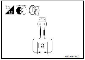
Check front outside handle (request switch).
 Trunk lamp switch
Description
Detects trunk open/close condition.
Component Function Check
1. CHECK FUNCTION
With CONSULT
Check TRNK/HAT MNTR in Data Monitor mode with CONSULT.
Diagnosis Procedure
...
 Trunk opener request switch
Description
Performs trunk lid open request when it is pressed.
Component Function Check
1. CHECK FUNCTION
With CONSULT
Check trunk opener request switch REQ SW -BD/TR in Data Monitor mode.
...
Other materials:
Drinking alcohol/drugs and driving
WARNING
Never drive under the influence of alcohol
or drugs. Alcohol in the bloodstream reduces
coordination, delays reaction time
and impairs judgement. Driving after
drinking alcohol increases the likelihood
of being involved in an accident injuring
yourself and others. Additionally, if you ...
AV control unit
Removal and Installation
AV control unit
AV control unit bracket (LH)
AV control unit bracket (RH)
A/C auto amp.
Cluster lid C (with A/C and AV switch
assembly attached)
Clip
AV CONTROL UNIT
Removal
CAUTION:
Before replacing AV control unit, perform "READ CONFIGURATI ...
B2110 transmission range switch
Description
IPDM E/R confirms the shift position with the following
signals.
Transmission range switch
Shift position signal from BCM (CAN)
DTC Logic
DTC DETECTION LOGIC
NOTE:
If DTC B2110 is displayed with DTC
U1000, first perform the trouble diagnosi ...
Nissan Maxima Owners Manual
- Illustrated table of contents
- Safety-Seats, seat belts and supplemental restraint system
- Instruments and controls
- Pre-driving checks and adjustments
- Monitor, climate, audio, phone and voice recognition systems
- Starting and driving
- In case of emergency
- Appearance and care
- Do-it-yourself
- Maintenance and schedules
- Technical and consumer information
Nissan Maxima Service and Repair Manual

0.0055