Nissan Maxima Service and Repair Manual: P0776 pressure control solenoid B
Description
The secondary pressure solenoid valve regulates the secondary pressure to suit the driving condition in response to a signal sent from the TCM.
DTC Logic
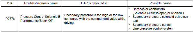
DTC DETECTION LOGIC
DTC CONFIRMATION PROCEDURE
CAUTION: Always drive vehicle at a safe speed.
NOTE: Immediately after performing any "DTC CONFIRMATION PROCEDURE", always turn ignition switch OFF.
Then wait at least 10 seconds before performing the next test.
1.CHECK DTC DETECTION
 With CONSULT
- Turn ignition switch ON.
- Select "Data Monitor" in "TRANSMISSION".
- Start engine and maintain the following conditions for at least 30 consecutive seconds.
ATF TEMP SEN : 1.0 − 2.0 V
ACC PEDAL OPEN : More than 1.0/8
RANGE : "D" position
VEHICLE SPEED : 10 km/h (6 MPH) or more
Driving location : Driving the vehicle uphill (increased engine load) will help maintain the driving conditions required for this test.
 With GST
Follow the procedure "With CONSULT".
Diagnosis Procedure
1.CHECK LINE PRESSURE
Perform line pressure test. Refer to TM-162, "Inspection and Judgment".
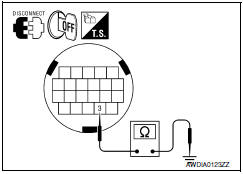
2.CHECK SECONDARY PRESSURE SOLENOID VALVE
- Turn ignition switch OFF.
- Disconnect CVT unit connector.
- Check secondary pressure solenoid valve. Refer to TM-76, "Component Inspection (Secondary Pressure Solenoid Valve)".
3.CHECK LINE PRESSURE SOLENOID VALVE
Check line pressure solenoid valve. Refer to TM-76, "Component Inspection (Line Pressure Solenoid Valve)".
4.CHECK SECONDARY PRESSURE SENSOR SYSTEM
Check secondary pressure sensor system. Refer to TM-85, "DTC Logic".
5.DETECT MALFUNCTIONING ITEMS
Check TCM connector pin terminals for damage or loose connection with harness connector.
Component Inspection (Line Pressure Solenoid Valve)
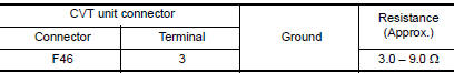
1.CHECK LINE PRESSURE SOLENOID VALVE
Check resistance between CVT unit connector terminal and ground.
Component Inspection (Secondary Pressure Solenoid Valve)
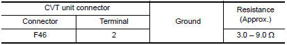
1.CHECK SECONDARY PRESSURE SOLENOID VALVE
Check resistance between CVT unit connector terminal and ground.
 P0746 pressure control solenoid A
Description
The line pressure solenoid valve regulates the oil pump discharge pressure to
suit the driving condition in
response to a signal sent from the TCM.
DTC Logic
DTC DETECTION LOGIC
...
 P0778 pressure control solenoid B
Description
The secondary pressure solenoid valve regulates the oil pump discharge
pressure to suit the driving condition
in response to a signal sent from the TCM.
DTC Logic
DTC DETECTION LOGI ...
Other materials:
Cleaning exterior
In order to maintain the appearance of your vehicle,
it is important to take proper care of it.
To protect the paint surfaces, please wash your
vehicle as soon as you can:
after a rainfall to prevent possible damage
from acid rain
after driving on coastal roads
when contaminants such ...
Can communication
System Description
CAN (Controller Area Network) is a serial communication line for real time
application. It is an on-vehicle multiplex
communication line with high data communication speed and excellent error
detection ability. Many electronic
control units are equipped onto a vehicle, an ...
U1244 GPS antenna
DTC Logic
Diagnosis Procedure
1.GPS ANTENNA CHECK
Inspect GPS antenna and antenna feeder for damage or poor connection.
2.CHECK AV CONTROL UNIT VOLTAGE
Turn ignition switch ON.
Check voltage between AV control unit connector M165 terminal
105 and ground.
...
Nissan Maxima Owners Manual
- Illustrated table of contents
- Safety-Seats, seat belts and supplemental restraint system
- Instruments and controls
- Pre-driving checks and adjustments
- Monitor, climate, audio, phone and voice recognition systems
- Starting and driving
- In case of emergency
- Appearance and care
- Do-it-yourself
- Maintenance and schedules
- Technical and consumer information
Nissan Maxima Service and Repair Manual

0.0088