Nissan Maxima Service and Repair Manual: Diagnosis and repair workflow
Work Flow
OVERALL SEQUENCE
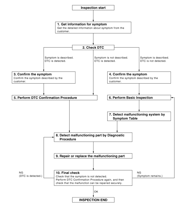
DETAILED FLOW
1. GET INFORMATION FOR SYMPTOM
Get the detailed information from the customer about the symptom (the condition and the environment when the incident/malfunction occurred).
2. CHECK DTC
- Check DTC.
- Perform the following procedure if DTC is displayed.
- Record DTC and freeze frame data (Print them out with CONSULT.)
- Erase DTC.
- Study the relationship between the cause detected by DTC and the symptom described by the customer.
- Check related service bulletins for information.
3. CONFIRM THE SYMPTOM
Confirm the symptom described by the customer.
Connect CONSULT to the vehicle in "DATA MONITOR" mode and check real time diagnosis results.
Verify relation between the symptom and the condition when the symptom is detected.
4. CONFIRM THE SYMPTOM
Confirm the symptom described by the customer.
Connect CONSULT to the vehicle in "DATA MONITOR" mode and check real time diagnosis results.
Verify relation between the symptom and the condition when the symptom is detected
5. PERFORM DTC CONFIRMATION PROCEDURE
Perform DTC Confirmation Procedure for the displayed DTC, and then check that DTC is detected again.
At this time, always connect CONSULT to the vehicle, and check diagnostic results in real time.
If two or more DTCs are detected, refer to BCS-63, "DTC Inspection Priority Chart" and determine trouble diagnosis order.
NOTE:
- Freeze frame data is useful if the DTC is not detected.
- Perform Component Function Check if DTC Confirmation Procedure
is not included in Service Manual. This
simplified check procedure is an effective alternative though DTC cannot be
detected during this check.
If the result of Component Function Check is NG, it is the same as the detection of DTC by DTC Confirmation Procedure.
6. PERFORM BASIC INSPECTION
7. DETECT MALFUNCTIONING SYSTEM BY SYMPTOM TABLE
Detect malfunctioning system based on the confirmed symptom in step 4, and determine the trouble diagnosis order based on possible causes and symptom.
8. DETECT MALFUNCTIONING PART BY DIAGNOSTIC PROCEDURE
Inspect according to Diagnostic Procedure of the system.
NOTE: The Diagnostic Procedure described based on open circuit inspection. A short circuit inspection is also required for the circuit check in the Diagnostic Procedure.
9. REPAIR OR REPLACE THE MALFUNCTIONING PART
- Repair or replace the malfunctioning part.
- Reconnect parts or connectors disconnected during Diagnostic Procedure again after repair and replacement.
- Check DTC. If DTC is displayed, erase it.
10. FINAL CHECK
When DTC was detected in step 2, perform DTC Confirmation Procedure or Component Function Check again, and then check that the malfunction has been repaired securely.
When symptom was described from the customer, refer to confirmed symptom in step 3 or 4, and check that the symptom is not detected.
 Basic inspection
...
 Inspection and adjustment
ADDITIONAL SERVICE WHEN REMOVING BATTERY NEGATIVE TERMINAL
ADDITIONAL SERVICE WHEN REMOVING BATTERY NEGATIVE TERMINAL : Description
Initial setting is necessary when battery terminal is removed.
CA ...
Other materials:
DLC branch line circuit
Diagnosis Procedure
1.CHECK CONNECTOR
Turn the ignition switch OFF.
Disconnect the battery cable from the negative terminal.
Check the terminals and connectors of the data link connector for
damage, bend and loose connection
(connector side and harness side).
2.CHECK HARNESS FOR OP ...
Inspection and adjustment
ADDITIONAL SERVICE WHEN REPLACING CONTROL UNIT
ADDITIONAL SERVICE WHEN REPLACING CONTROL UNIT : Description
Initialization of system should be conducted after the following conditions.
When the sunroof motor or sunshade motor is changed.
When the sunroof of sunshade does not operate normally ...
Rear sunshade
Removal and Installation
Rear sunshade unit Front
REMOVAL
Remove the rear parcel shelf finisher. Refer to INT-24, "Removal
and Installation".
Remove the rear sunshade unit.
Remove the rear sunshade unit bolts.
Disconnect the rear sunshade unit harness
connector ...
Nissan Maxima Owners Manual
- Illustrated table of contents
- Safety-Seats, seat belts and supplemental restraint system
- Instruments and controls
- Pre-driving checks and adjustments
- Monitor, climate, audio, phone and voice recognition systems
- Starting and driving
- In case of emergency
- Appearance and care
- Do-it-yourself
- Maintenance and schedules
- Technical and consumer information
Nissan Maxima Service and Repair Manual

0.0179