Nissan Maxima Service and Repair Manual: P0778 pressure control solenoid B
Description
The secondary pressure solenoid valve regulates the oil pump discharge pressure to suit the driving condition in response to a signal sent from the TCM.
DTC Logic
DTC DETECTION LOGIC
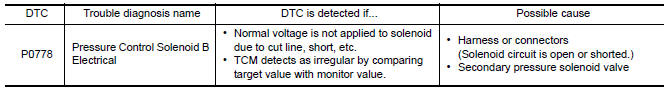
DTC CONFIRMATION PROCEDURE
CAUTION: Always drive vehicle at a safe speed.
NOTE: Immediately after performing any "DTC CONFIRMATION PROCEDURE", always turn ignition switch OFF.
Then wait at least 10 seconds before performing the next test.
1.CHECK DTC DETECTION
 With CONSULT
- Start engine.
- Drive vehicle and maintain the following conditions for at least 5 consecutive seconds.
- Perform "Self Diagnostic Results" in "TRANSMISSION".
 With GST
Follow the procedure "With CONSULT".
Diagnosis Procedure
Regarding Wiring Diagram information, refer to TM-126, "Wiring Diagram".
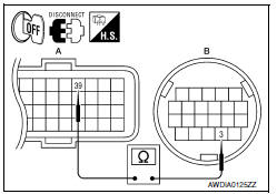
1.CHECK SECONDARY PRESSURE SOLENOID VALVE CIRCUIT
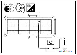
- Turn ignition switch OFF.
- Disconnect TCM connector.
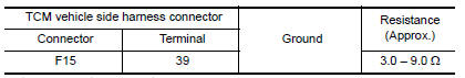
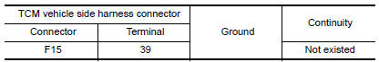
- Check resistance between TCM vehicle side harness connector terminal and ground.
2.CHECK HARNESS BETWEEN TCM AND SECONDARY PRESSURE SOLENOID VALVE (PART 1)
- Disconnect CVT unit connector.
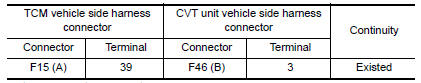
- Check continuity between TCM vehicle side harness connector terminal and CVT unit vehicle side harness connector terminal.
3.CHECK HARNESS BETWEEN TCM AND SECONDARY PRESSURE SOLENOID VALVE (PART 2
Check continuity between TCM vehicle side harness connector terminal and ground.
4.CHECK SECONDARY PRESSURE SOLENOID VALVE
Check secondary pressure solenoid valve. Refer to TM-78, "Component Inspection (Secondary Pressure Solenoid Valve)".
5.DETECT MALFUNCTIONING ITEMS
Check TCM connector pin terminals for damage or loose connection with harness connector.
Component Inspection (Secondary Pressure Solenoid Valve)
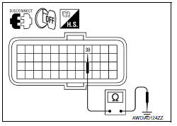
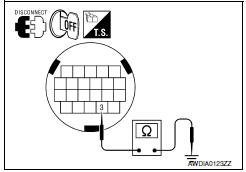
1.CHECK SECONDARY PRESSURE SOLENOID VALVE
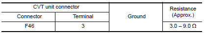
Check resistance between CVT unit connector terminal and ground.
 P0776 pressure control solenoid B
Description
The secondary pressure solenoid valve regulates the secondary pressure to
suit the driving condition in
response to a signal sent from the TCM.
DTC Logic
DTC DETECTION LOGIC
DTC ...
 P0826 up and down shift SW
Description
Manual mode switch transmits signals (manual mode, not manual mode, shift up
and shift down) to combination
meter.
Paddle shifter transmits signals (shift up and shift down) to combi ...
Other materials:
Mechanical key
The Intelligent Key contains the mechanical key,
which can be used in case of a discharged battery.
To remove the mechanical key, release the lock
knob on the back of the Intelligent Key.
To install the mechanical key, firmly insert it into
the Intelligent Key until the lock knob return ...
Rear window glass
Exploded View
Rear window glass
Spacer
Rubber dam (if equipped)
Primer
Rear window molding
Adhesive
16 +2, -0 mm (0.63 +0.08, - 0 in)
7+ 2, - 0 mm (0.28 + 0.08, - 0 in)
12+ 2, - 0 mm (0.47 + 0.08, - 0 in)
Removal and Installation
REMOVAL
Partiall ...
Precaution
Precaution for Supplemental Restraint System (SRS) "AIR BAG" and "SEAT
BELT
PRE-TENSIONER"
The Supplemental Restraint System such as "AIR BAG" and "SEAT BELT PRE-TENSIONER",
used along
with a front seat belt, helps to reduce the risk or severity of injury to the
driver ...
Nissan Maxima Owners Manual
- Illustrated table of contents
- Safety-Seats, seat belts and supplemental restraint system
- Instruments and controls
- Pre-driving checks and adjustments
- Monitor, climate, audio, phone and voice recognition systems
- Starting and driving
- In case of emergency
- Appearance and care
- Do-it-yourself
- Maintenance and schedules
- Technical and consumer information
Nissan Maxima Service and Repair Manual

0.0085