Nissan Maxima Service and Repair Manual: P0826 up and down shift SW
Description
Manual mode switch transmits signals (manual mode, not manual mode, shift up and shift down) to combination meter.
Paddle shifter transmits signals (shift up and shift down) to combination meter. (With paddle shifter) Combination meter transmits signals (manual mode, not manual mode, shift up and shift down) to TCM with CAN communication signal.
DTC Logic
DTC DETECTION LOGIC
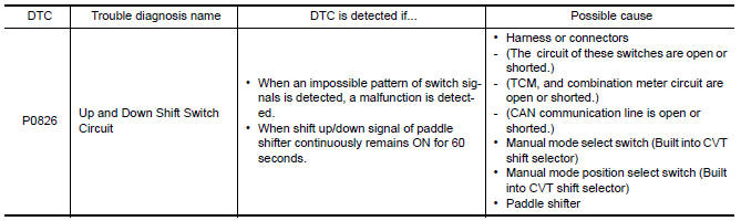
DTC CONFIRMATION PROCEDURE
CAUTION: Always drive vehicle at a safe speed.
NOTE: If "DTC CONFIRMATION PROCEDURE" has been previously performed, always turn ignition switch OFF.
Then wait at least 10 seconds before performing the next test.
1.CHECK DTC DETECTION
 With CONSULT
- Turn ignition switch ON.
- Select "Data Monitor" in "TRANSMISSION".
- Drive vehicle and maintain the following conditions for at least 2 consecutive seconds.
MMODE : On
Diagnosis Procedure
Regarding Wiring Diagram information, refer to TM-126, "Wiring Diagram".
1.CHECK MANUAL MODE SWITCH SIGNALS
 With CONSULT
- Turn ignition switch ON.
- Select "Data Monitor" in "TRANSMISSION".
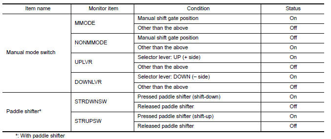
- Check the On/Off operations of each monitor item.
 Without CONSULT
Drive vehicle in the manual mode, and confirm that the actual gear position and the meter's indication of the position mutually coincide when the selector lever and paddle shifter* are shifted to the "+ (up)" or "− (down)" side (1st ⇔ 6th gear).
*: With paddle shifter
2.CHECK MANUAL MODE SWITCH
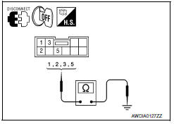
- Turn ignition switch OFF.
- Disconnect CVT shift selector connector.
- Check manual mode switch. Refer to TM-83, "Component Inspection (Manual Mode Switch)".
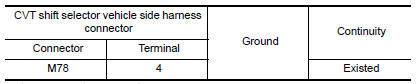
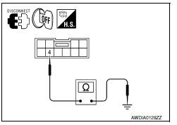
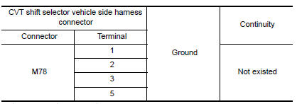
3.CHECK GROUND CIRCUIT (PART 1)
Check continuity between CVT shift selector vehicle side harness connector terminal and ground.
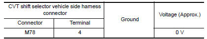
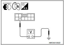
4.CHECK GROUND CIRCUIT (PART 2)
Check voltage between CVT shift selector vehicle side harness connector terminal and ground.
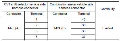
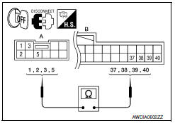
5.CHECK HARNESS BETWEEN CVT SHIFT SELECTOR AND COMBINATION METER (PART 1)
- Disconnect combination meter connector.
- Check continuity between CVT shift selector vehicle side harness connector terminals and combination meter vehicle side harness connector terminals.
6.CHECK HARNESS BETWEEN CVT SHIFT SELECTOR AND COMBINATION METER (PART 2)
Check continuity between CVT shift selector vehicle side harness connector terminals and ground.
7.CHECK PADDLE SHIFTER
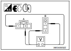
- Turn ignition switch OFF.
- Disconnect paddle shifter connector.
- Turn ignition switch ON.
- Check voltage between paddle shifter side harness connector terminals.
8.CHECK PADDLE SHIFTER
Check paddle shifter. Refer to TM-84, "Component Inspection (Paddle Shifter)".
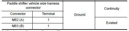
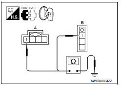
9.CHECK GROUND CIRCUIT
Check continuity between paddle shifter vehicle side harness connector terminal and ground.
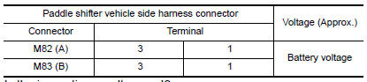
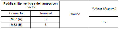
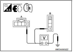
10.CHECK POWER SOURCE CIRCUIT
Check voltage between paddle shifter vehicle side harness connector terminal and ground.
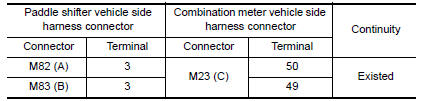
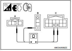
11.CHECK HARNESS BETWEEN PADDLE SHIFTER AND COMBINATION METER (PART 1)
- Disconnect combination meter connector.
- Check continuity between paddle shifter vehicle side harness connector terminals and combination meter vehicle side harness connector terminals.
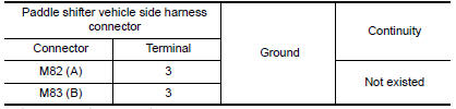
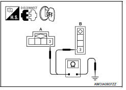
12.CHECK HARNESS BETWEEN PADDLE SHIFTER AND COMBINATION METER (PART 2)
Check continuity between paddle shifter vehicle side harness connector terminals and ground.
13.DETECT MALFUNCTIONING ITEMS
Check TCM connector pin terminals for damage or loose connection with harness connector.
Component Inspection (Manual Mode Switch)
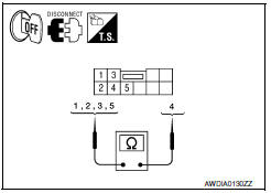
1.CHECK MANUAL MODE SWITCH
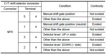
Check continuity between CVT shift selector connector terminals.
Component Inspection (Paddle Shifter)
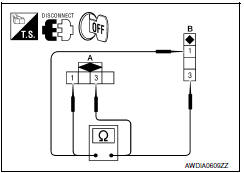
1.CHECK PADDLE SHIFTER
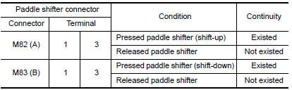
Check continuity between paddle shifter connector terminals.
 P0778 pressure control solenoid B
Description
The secondary pressure solenoid valve regulates the oil pump discharge
pressure to suit the driving condition
in response to a signal sent from the TCM.
DTC Logic
DTC DETECTION LOGI ...
 P0840 transmission fluid pressure SEN/SW A
The secondary pressure sensor detects secondary pressure of CVT and sends a
signal to the TCM.
DTC Logic
DTC DETECTION LOGIC
DTC CONFIRMATION PROCEDURE
NOTE:
Immediately after performing any ...
Other materials:
Removal and installation
IPDM E/R (INTELLIGENT POWER DISTRIBUTION MODULE ENGINE
ROOM)
Removal and Installation
CAUTION:
Do not remove the relays from the IPDM E/R. Tampering with the relays may cause
additional incidents
with the vehicle.
REMOVAL
Disconnect battery negative terminal. Refer to PG-67, " ...
B260f engine status
Description
BCM receives the engine status signal from ECM via CAN
communication.
DTC Logic
DTC DETECTION LOGIC
NOTE:
If DTC B260F is displayed with DTC
U1000, first perform the trouble diagnosis for DTC U1000. Refer to
SEC-29, "DTC Logic".
If DTC B260F is displayed with D ...
Adjusting the screen
1. Touch the touch-screen display with the
Around View Monitor on.
2. Touch the "Brightness," "Contrast," "Tint,"
"Color," or "Black Level" key.
3. Adjust the item by touching the + or - key
on the touch-screen display.
NOTE:
Do not adjust any of the display settings of
the Around Vi ...
Nissan Maxima Owners Manual
- Illustrated table of contents
- Safety-Seats, seat belts and supplemental restraint system
- Instruments and controls
- Pre-driving checks and adjustments
- Monitor, climate, audio, phone and voice recognition systems
- Starting and driving
- In case of emergency
- Appearance and care
- Do-it-yourself
- Maintenance and schedules
- Technical and consumer information
Nissan Maxima Service and Repair Manual

0.0195