Nissan Maxima Service and Repair Manual: P0746 pressure control solenoid A
Description
The line pressure solenoid valve regulates the oil pump discharge pressure to suit the driving condition in response to a signal sent from the TCM.
DTC Logic
DTC DETECTION LOGIC
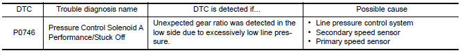
DTC CONFIRMATION PROCEDURE
CAUTION: Always drive vehicle at a safe speed.
NOTE: Immediately after performing any "DTC CONFIRMATION PROCEDURE", always turn ignition switch OFF.
Then wait at least 10 seconds before performing the next test.
1.CHECK DTC DETECTION
 With CONSULT
- Turn ignition switch ON.
- Select "Data Monitor" in "TRANSMISSION".
- Start engine and maintain the following conditions for at least 10 consecutive seconds. Test start from 0 km/h (0 MPH).
ATF TEMP SEN : 1.0 − 2.0 V
ACC PEDAL OPEN : More than 1.0/8
RANGE : "D" position
VEHICLE SPEED : 10 km/h (6 MPH) or more
Driving location : Driving the vehicle uphill (increased engine load) will help maintain the driving conditions required for this test.
 With GST
Follow the procedure "With CONSULT".
Diagnosis Procedure
1.CHECK LINE PRESSURE
Perform line pressure test. Refer to TM-162, "Inspection and Judgment".
2.CHECK LINE PRESSURE SOLENOID VALVE
- Turn ignition switch OFF.
- Disconnect CVT unit connector.
- Check line pressure solenoid valve. Refer to TM-74, "Component Inspection (Line Pressure Solenoid Valve)".
3.CHECK SECONDARY SPEED SENSOR SYSTEM
Check secondary speed sensor system. Refer to TM-60, "DTC Logic".
4.CHECK PRIMARY SPEED SENSOR SYSTEM
Check primary speed sensor system. Refer to TM-57, "DTC Logic".
5.DETECT MALFUNCTIONING ITEMS
Check TCM connector pin terminals for damage or loose connection with harness connector.
Component Inspection (Line Pressure Solenoid Valve)
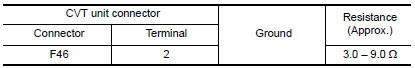
1.CHECK LINE PRESSURE SOLENOID VALVE
Check resistance between CVT unit connector terminal and ground.
 P0745 pressure control solenoid A
Description
The line pressure solenoid valve regulates the oil pump discharge pressure to
suit the driving condition in
response to a signal sent from the TCM.
DTC Logic
DTC DETECTION LOGIC
...
 P0776 pressure control solenoid B
Description
The secondary pressure solenoid valve regulates the secondary pressure to
suit the driving condition in
response to a signal sent from the TCM.
DTC Logic
DTC DETECTION LOGIC
DTC ...
Other materials:
DTC B2205 vehicle speed circuit
Description
The ABS actuator and electric unit (control unit) provides a vehicle speed
signal to the combination meter via
CAN communication lines.
DTC Logic
Diagnosis Procedure
Symptom: Displays "VEHICLE SPEED CIRC [B2205]" as a self-diagnosis result of
combination meter.
1.CHECK COMBI ...
Satellite radio antenna
Removal and Installation
REMOVAL
Lower the headlining at the rear. Refer to INT-33, "Exploded
View".
Disconnect the harness connector (A) from satellite radio
antenna.
Remove the satellite radio antenna nut (B) and the satellite radio
antenna (1).
INSTALLATION
Installation is ...
Additional service when replacing control unit (bcm)
ADDITIONAL SERVICE WHEN REPLACING CONTROL UNIT (BCM) : Description
BEFORE REPLACEMENT
When replacing BCM, save or print current vehicle specification with CONSULT
configuration before replacement.
NOTE:
If "Before Replace ECU" cannot be used, use the "After Replace ECU" or ...
Nissan Maxima Owners Manual
- Illustrated table of contents
- Safety-Seats, seat belts and supplemental restraint system
- Instruments and controls
- Pre-driving checks and adjustments
- Monitor, climate, audio, phone and voice recognition systems
- Starting and driving
- In case of emergency
- Appearance and care
- Do-it-yourself
- Maintenance and schedules
- Technical and consumer information
Nissan Maxima Service and Repair Manual

0.0078