Nissan Maxima Service and Repair Manual: U1300 AV comm circuit
Description
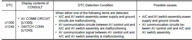
U1300 is indicated when a communication signal malfunction occurs. U1300 is indicated along with DTCs that identify components connected to the AV control unit through communication lines. Determine the possible malfunction cause from the table below.
SELF-DIAGNOSIS RESULTS DISPLAY ITEM
 U1255 satellite radio tuner
Description
DTC Logic
Diagnosis Procedure
1.CHECK SATELLITE RADIO TUNER POWER SUPPLY AND GROUND CIRCUIT
Check satellite radio tuner power supply and ground circuit.
2.CHECK CONTINUITY COM ...
 U1310 AV control unit
Description
DTC Logic
...
Other materials:
Suspension ARM
Removal and Installation
Removal
Remove the rear suspension member. Refer to RSU-16, "Removal and
Installation".
Remove the connecting rod mount bracket nut and bolt from the rear
suspension arm using power tools.Remove the connecting rod mount
bracket.
Remove each rear suspension ...
Precaution
PRECAUTIONS
Precaution for Supplemental Restraint System (SRS) "AIR BAG" and "SEAT
BELT
PRE-TENSIONER"
The Supplemental Restraint System such as "AIR BAG" and "SEAT BELT
PRE-TENSIONER", used along
with a front seat belt, helps to reduce the risk or severity of injury to ...
Sunroof motor assembly
Wiring Diagram
...
Nissan Maxima Owners Manual
- Illustrated table of contents
- Safety-Seats, seat belts and supplemental restraint system
- Instruments and controls
- Pre-driving checks and adjustments
- Monitor, climate, audio, phone and voice recognition systems
- Starting and driving
- In case of emergency
- Appearance and care
- Do-it-yourself
- Maintenance and schedules
- Technical and consumer information
Nissan Maxima Service and Repair Manual

0.007