Nissan Maxima Service and Repair Manual: U1255 satellite radio tuner
Description
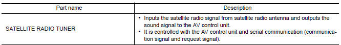
DTC Logic
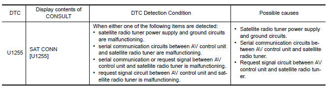
Diagnosis Procedure
1.CHECK SATELLITE RADIO TUNER POWER SUPPLY AND GROUND CIRCUIT
Check satellite radio tuner power supply and ground circuit.
2.CHECK CONTINUITY COMMUNICATION CIRCUIT AND REQUEST SIGNAL CIRCUIT
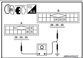
- Turn ignition switch OFF.
- Disconnect AV control unit connector M153 and satellite radio tuner connector B111.
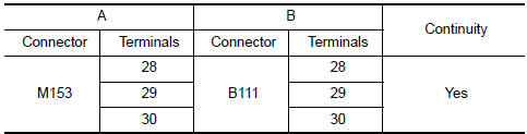
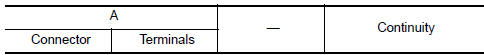
- Check continuity between AV control unit harness connector M153 (A) and satellite radio tuner harness connector B111 (B).
- Check continuity between AV control unit harness connector M153 (A) and ground.
3.CHECK AV CONTROL UNIT VOLTAGE
- Connect AV control unit connector.
- Turn ignition switch ON.
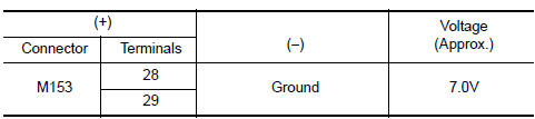
- Check voltage between AV control unit harness connector M153 and ground.
4.CHECK SATELLITE RADIO TUNER
- Turn ignition switch OFF.
- Disconnect AV control unit connector.
- Connect satellite radio tuner.
- Turn ignition switch ON.
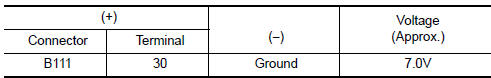
- Check voltage between satellite radio tuner harness connector terminal ground.
 U1263 USB
DTC Logic
Diagnosis Procedure
1.CHECK USB HARNESS
Visually check USB harness. ...
 U1300 AV comm circuit
Description
U1300 is indicated when a communication signal malfunction occurs. U1300 is
indicated along with DTCs that
identify components connected to the AV control unit through communication
...
Other materials:
Subwoofer
Removal and Installation
Subwoofer (LH)
Subwoofer (RH)
Subwoofer screws
Subwoofer connectors
REMOVAL
Remove the rear parcel shelf finisher. Refer to INT-28, "Removal
and Installation".
Remove the subwoofer screws.
Pull out the subwoofer, disconnect the h ...
Difference between predicted and actual distances
The displayed guidelines and their locations on
the ground are for approximate reference only.
Objects on uphill or downhill surfaces or projecting
objects will be actually located at distances
different from those displayed in the monitor relative
to the guidelines (refer to illustrations). ...
Trunk room lamp circuit
Description
Controls the trunk room lamp (ground side) to turn the trunk room lamp ON and
OFF.
Component Function Check
CAUTION: Before performing the diagnosis,
check that the following is normal.
Battery saver output/power supply
Trunk room lamp bulb
1.CHECK TRUNK ROOM LAMP OPERATI ...
Nissan Maxima Owners Manual
- Illustrated table of contents
- Safety-Seats, seat belts and supplemental restraint system
- Instruments and controls
- Pre-driving checks and adjustments
- Monitor, climate, audio, phone and voice recognition systems
- Starting and driving
- In case of emergency
- Appearance and care
- Do-it-yourself
- Maintenance and schedules
- Technical and consumer information
Nissan Maxima Service and Repair Manual

0.005